![]()
![]()
feels good, dose more
MANUAL
V 1.07
D&R Electronica B.V., Rijnkade 15B, 1382GS Weesp, Netherlands
Phone: +31 (0)294-418014 | Website: www.dnrbroadcast.com | Imel: sales@dr.nl
WebManajan Kanfigareshan Tasha Software
Ya ku Abokin ciniki,
Thank you for choosing the D&R WEBSTATION mixer.
The webstation was designed by radio broadcast professionals along with the d&r design team and is intended to be used 24 hours per day as an “on-air” mixer and/or a production console in the most demanding production room.
We are confident that you will be using the webstation mixer for many years to come, and wish you much success.
We value suggestions from our clients and would be grateful if you could email us with your comments when you are familiar with the webstation mixer.
Muna koya daga ra'ayoyi da shawarwarin abokan ciniki kamar ku kuma muna godiya da lokacin da kuka ɗauka don yin hakan a ƙarshe.
And… we always appreciate nice studio pictures with the webstation in use to include on our website.
Da fatan za a aika su zuwa ga sales@dr.nl
with kind regards,
Duco de Rijk
MD
SHIGA SOFTWARE
- Download the latest software and/or firmware from the D&R WIKI page:
https://www.dnrbroadcast.com/user-manuals - Shigar da Software
o Doubleclick the executable (.exe) file kuma bi umarnin kan allon. - Sabunta firmware
o Install the new firmware with the D&R Firmware Updatetool (See chapter 1.5)
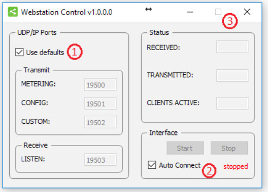
1.1 Webstation Control
![]() Webstation Control is required to install to provide a communication interface between the Webstation console and other applications (i.e. Webstation Meters).
Webstation Control is required to install to provide a communication interface between the Webstation console and other applications (i.e. Webstation Meters).
The application runs at the background and connects to the console automatically when its USB-main port is connected to the PC.
- Danna sau biyu Webstation Control vx.x.x.x – Setup.exe
- Follow the installation instructions on the screen
- If installation was successful you will see the Webstation Control icon in the taskbar
- Richt-click on the icon and click on Settings
- Make sure the two checkboxes are checked and close the window
- Connect the USB-main port of the console with the PC
- Webstation Control automatically starts running when a console is connected:
1.2 Webstation Meters
Webstation Meters is an application which shows metering levels and states of the Webstation console.
The six buttons in the lower section of the meter screen indicate which source is selected and are also functioning as the Channel ON switch when clicked with a mouse (or touch screen) The NONSTOP indicator can also be used as remote control by clicking on it.
- Danna sau biyu Webstation Meters vx.x.x.x – Setup.exe
- Follow the installation instructions on the screen
- Double click on the icon on your desktop to run the application
- Press the settings symbol in the upper right corner
- Set remote host to: 127.0.0.1
- Check the Use defaults checkbox and press [OK]
- A green line below the D&R logo indicates the application is online (receiving data)

1.3 Webstation Configuration Manager
![]()
Webstation Configuration Manager can be used to read or write configuration settings from or to the Webstation console respectively.
The entire configuration can be saved or loaded as a preset-file daga File menu.
- Danna sau biyu Webstation Configuration Manager vx.x.x.x – Setup.exe
- Follow the installation instructions on the screen
- Double click on the icon on your desktop to run the application
- Press the Options->Communication from the menu bar:
- Set remote host to: 127.0.0.1
- Check the Use defaults checkbox and press [OK]
- Press [READ] to read configuration settings from the console.

1.4 Webstation Voip
![]() Webstation Voip is an application which let you answer or end calls from a voip application (only Skype supported at the moment) with the [CONNECT] button on module 8 of the Webstation console.
Webstation Voip is an application which let you answer or end calls from a voip application (only Skype supported at the moment) with the [CONNECT] button on module 8 of the Webstation console.
Danna sau biyu Webstation Voip vx.x.x.x – Setup.exe
Follow the installation instructions on the screen
The application runs automatically when the PC is started.
1.5 Firmware Updatetool
Firmware Updatetool can be used to update the internal firmware of the Webstation console.
The latest firmware can be downloaded from the D&R WIKI page:
https://www.dnrbroadcast.com/user-manuals
- Double click on Firmware Updatetool vx.x – Setup.exe
- Follow the installation instructions on the screen
- Double click on the icon on your desktop to run the application
- Make sure the console is in bootloader mode:
• Power off the console
• Press and hold on the CONNECT button (located in channel 8, VoIP)
• Power on the console
• Release CONNECT button - Select D&R Webstation from the device list
- Zaɓi firmware file (*.hex)
- Press [UPDATE]
- When update was successful a window similar as below will popup:
INTRODUCTION MIXER UNIT
NOTE: To avoid any problems with grounding potential differences that might cause input circuit damage.
Please switch both the WEBSTATION and other equipment off before connecting to each other.
Sannan kunna WEBSTATION on and then your connected equipment.


2.1 MIC / LINE MODULES 1-2
- 2x Professional extremely low noise balanced Mic pre-amps with 48 volt phantom powering on XLR.
- Two stereo line inputs.
- Every input with insert for processors.
- Gain control to adjust the incoming mic or line level.
- Two band stereo equalizer.
- Canjin sitiriyo CUE don sauraron riga-kafi.
- ON switch. (also voicetrack buss activation)
- 100 mm professional N-Alps fader with fader start.
- Stereo VCA fader control.
2.2 USB / LINE MODULES 3-5
- Input selectable between USB or stereo Line.
- Gain control for incoming signals.
- Canjin sitiriyo CUE don sauraron riga-kafi.
- ON canza.
- 100 mm professional N-Alps fader with fader start.
- Stereo VCA fader control.
2.3 VOIP/ LINE MODULE 6
- Input selectable between VoIP or stereo Line.
- Stereo line input can be used for external Hybrid.
- Gain control for incoming signals.
- VoIP send control for outgoing level.
- Canjin sitiriyo CUE don sauraron riga-kafi.
- ON canza.
- 100 mm professional N-Alps fader with fader start.
- Stereo VCA fader control.
2.4 BAYANIN MALAMAI
- Master controls for Phones/CRM
- CRM section with Cue Reset and Auto Cue.
- NON-STOP switch routes module 3 (USB stereo input) directly to the main program Cinch connectors.
- 12 free programmabled control switches for music play-out systems.
- Built in Voice Tracking buss.
- Cue bus is also communication buss
2.5 SOFTWARE
- All Software is available from the D&R WIKI page:
https://www.dnrbroadcast.com/user-manuals - All modules individually programmable
- Many Master functions individually programmable.
- USB control section allows play-out software to be controlled by the mixer.
SIGON SALATI

WEBSTATION BACKPANEL
The back panel shows all the in and output connectors to interface with your other equipment.
The first two of modules 1-2 MIC/LINE modules on the right have balanced XLR mic inputs with a mic insert for voice processing.
Two cinch connectors accept line level left/right input signals.

Modules 3-4-5 are the USB inputs that are fed from a built in USB HUB that accepts and sends stereo sends signals to a connected PC where a music play-out systems could be active.
There are also stereo line inputs available on Cinch connectors per input 3-4-5. (6)
The module backpanel also houses the USB connector for both the audio and the VoIP connection.
The USB connector carries all the 4 stereo audio signals to and from the PC (for both Windows & Macintosh computers) as well as the Play-out systems control info from the programmable Control section plus the Clock and meter information.
This USB feature will also allow you to connect to the Internet via your computer for “Live” streaming of audio to the Internet.
Module 6 (VoIP) has as extra a stereo line input for external (analog) Hybrids and cleanfeed outputs to drive these external Hybrids incase a VoIP connection is not available or not yet installed. This external Hybrid nees to be returned on the line inputs of the same VoIP channel.
4.1 MASTER CONNECTORS
The master section houses all the in and outputs of the controls on the front panel that will be discussed in more detail in other chapters.
Most of the functions are self explanatory, such as master right and left Cinch connctors and CRM cinch connectors for your monitoring.
Below the 4 Cinch connectors you see a stereo jack that is called Mic On.
Here you connect your On-AIR light on the tip and ring to show your microphone is active.
Worth mentioning is the heavy duty external power supply that accepts voltages between 85 en 260 volts AC 50/60Hz.

MIC / LINE INPUT MODULES 1-2
The input modules switches & controls of the Webstationmixer have the following functions:
Each of Modules 1 and 2 have two selectable inputs. The two types of inputs consist of a Microphone input and a stereo line input. In the lower Mic switch position, the module is a normal mono module. When the Mic is switched off (up position), you also have a stereo line level input to feed the stereo PROGRAM buss, CUE buss and Voice Tracking buss.

5.1 SAMU
With the gain control (the first control knob below the modules number), the source input level can be adjusted to the required internal mixer level. This control adjusts both the Mic input and the stereo line inputs with the same control depending on the switch position.
5.2 STEREO LINE
The stereo line input is a high impedance input ( >10 kOhm) for connecting the stereo line level outputs of devices such as CD players/MP3 players etc.
5.3 MIC
The Mic input has a balanced XLR input connector with 48 volt phantom powering for condenser mikes.
The Mic-pre circuitry uses the latest technology studio-class components as used in high end recording consoles. We use the That 1510 Mic-pre which is highly acclaimed for its low noise/distortion and transparent audio. The low-noise design and excellent phase spec that D&R is known for is integrated throughout the Webstation which results in a phase coherent signal path. Using balanced microphones & cables allows for the quietest and high quality audio signals throughout your Webstation mixer.
You can use standard balanced Mic cables available at any pro audio dealer or music store. The Webstation uses chassis-mount female XLR type Mic input connectors. Any standard pro audio Mic cable will fit into this female XLR connector.
5.4 MAI daidaitawa
Each module has a stereo two band equalizer to control the high and low frequencies individually. The D&R designers used carefully chosen frequencies in the equalizer circuitry to enhance the Mic input as well as the stereo line input.
5.5 CUE/COMMUNICATION BUSS
Below the LOW EQ potmeter is the stereo CUE switch (Pre Fade Listening).
This switch allows you to check the signal before you raise your channel fader up and mix it with other signals in the mixer. Another smart function is that this CUE bus can be used for communication. If you push a DJ’s Cue (let’s say channel one) and if you then push the Telco(VoIP) Cue (located in the TELCO(VoIP) module) , the DJ as well as the caller can hear each other outside the broadcast and even you, sitting behind the desk on the monitor speakers.
Lura: Levels need to be carefully set to avoid feedback and overdrive of circuits. The Cue switch also sends out HID(Human Interface Device) signal over USB that can be programmed to do specific functions in your play-out system.
5.6 AKAN
The ON switch is used to pass on the audio. The ON switch also sends out HID signal over USB that can be programmed to do specific functions in your play-out system. In the Control section of the manual we will explain how.
5.7 VOICE TRACK BUSS
The ON switch is ALSO used to route an input signal from module 1-2 to the Voice track buss.
Push the ON switch a little bit longer and the audio will be removed from the Program buss and assigned to the Voice track buss, as a result the ON switch will blink. The Voice track signal Is routed to USB-3 for further processing in your play-out system.
5.8 FADER
Final audio level control is the high quality, 100 mm long throw N-Alps channel fader that send out a control voltage to the internal stereo VCA. The control voltage is also used to detect when the fader is moved up and can send out a pulse for fader start purposes. This control voltage activates the start circuitry that can be assigned to one of the two GPO connectors.
A software page (as already seen on the next page) will be shown further in this manual to customize the Webstation to your needs with instructions how to do that.
5.9 INPUT CONNECTORS
On the back of modules 1 and 2, you find four connectors for each module. The stereo line input uses Cinch female type connectors.
Being un-balanced, the shield and (-) or out of phase signal wire need to be connected together and seen as ground during installation.

5.10 SHIGA
This ring/tip/sleeve stereo jack socket lets you insert signal processors such as compressors/gates or special voice processing units to improve your voice timbreto become the ultimate announcer/D.J.
The TIP of the stereo jack sends the PRE-FADER channel signal and the Ring accepts the return signal.
Below on the right you see the type of cable you need when your processor has jack in and outputs. Connect the tip from the stereo cable to the tip of one of the mono jacks and the ring of the stereo cable to the tip of the other mono jack.
Now insert the stereo jack into the Webstation’s insert and connect the mono jack that produces a hum when the ring is touched by your finger (and the related channel fader is open) into the processors output. The other mono jack should be inserted into the processors input.
In case your processor has XLR inputs connect the tip of the stereo jack to pin 2 of the Female XLR and short pin 1 and 3 with each other and connect to ground (sleeve). This also goes for the other Male XLR. Connect the ring of the stereo jack (which sends signals) to a male XLR pin2. Short here pin 1 and 3 and solder to ground (sleeve). This has to be done because the insert is not balanced.
See below the cable type you need.

5.11 SHIGA MAQROPHON
The Mic input is a balanced female XLR type connector., see the left connector below that should go into your mixer and your mic cable should end in a male XLR as seen on the right section of the picture.
1=Ground/shield
2=Hot (in phase)
3=Cold (out of Phase).

USB / LINE INPUT MODULES 3-4-5
The input modules switches & controls of the Webstation mixer have the following functions:
Each of Modules 3 thru 5 have two selectable inputs. The two types of inputs consist of an USB input and a stereo line input. In the lower USB switch position, the module is a stereo module. When the USB is switched off (up position), you also have a stereo line level input to feed the Master buss, Cue buss and Voice tracking buss.

6.1 SAMU
With the gain control (the first control knob below the modules number), the source input level can be adjusted to the required internal mixer level. This control adjusts both the USB input and the stereo Line inputs with the same control depending on the switch position.
6.2 STEREO LINE
The stereo line input is a high impedance input ( >10 kOhm) for connecting the stereo line level outputs of devices such as CD players/MP3 players etc.
6.3 USB
The USB stereo signal comes directly from one of the 3 stereo USB channels from your PC play-out software. These are already assigned in the Mixer to module 3, 4 and 5 by D&R.
6.4 CUE/COMMUNICATION BUSS
The stereo CUE switch (Pre Fade Listening) allows you to check the signal before you raise your channel fader up and mix it with other signals in the mixer.
Another smart function is that this CUE bus can be used for communication. If you push a DJ’s Cue (let’s say channel one) and if you then push the Telco Cue, the DJ as well as the caller can hear each other outside the broadcast and even you, sitting behind the desk on the monitor speakers.
Lura: Levels need to be carefully set to avoid feedback and overdrive of circuits.
The Cue switch also sends out HID signal over USB that can be programmed to do specific functions in your play-out system. In the Control section of the manual we will explain how.
6.5 AKAN
The ON switch also sends out HID signal over USB that can be programmed to do specific functions in your play-out system. In the Control section of the manual we will explain this how.
6.6 FADER
Final audio level control is the high quality, 100 mm long throw N-Alps channel fader that sends out a control voltage to the internal stereo VCA. The control voltage is also used to detect when the fader is moved up and sends out a pulse for fader start purposes.
6.7 SETTING UP THE USB MODULES
Actually there is not so much you can do concerning routing of the incoming USB signals. The ON switches connect the incoming stereo signals sent by the play-out system 1-3 to channel 3, 4 and 5.
The routing inside the PC software is done automatically and described in more detail below. In the Block diagram (in the brochure and in this manual) you can see that the mixers USB output signal 1 (all stereo) is the program signal and sent to the USB-1 buss. It is a PROG POST signal, it means a post channel stereo fader signal is sent to the USB connector and to your PC.
6.8 USB OUTPUTS
There are 4 stereo USB signals sent to your PC through the USB connector on the back of your console.
USB-1 = Main program signal.
USB-2 = Clean feed
USB-3 = Voice track signal
USB-4 = VoIP signal
An audio application needs to run on your PC to be able to see the levels. Otherwise trial and error is the only way. A free downloadable tool can be found here http://minorshill.co.uk/pc2/testgen.html
The return USB signal coming from the PC is fixed but can be adjusted with the webstation’s module gain controls.
6.9 SETTING UP THE MODULES
In order to set up a connection between your computer and the Webstation-USB mixer, only use the USB cable that is part of the shipment. When connecting the Webstation to your computer, the computer (PC or Mac) will recognize the Webstation as new hardware and will establish a connection to any audio programs needing audio hardware.
After establishing a connection, there is no need to download drivers or performing complicated setup routines, just plug in the USB cable to your Windows or Mac computer and start tracking! (or playing a maximum of 3 stereo channels at the same time).
Idan kana son ƙarin sani game da USB gwada wannan hanyar haɗin yanar gizon http://en.wikipedia.org/wiki/Audio_Stream_Input/Output
If you are already familiar with digital audio recording, the latest versions of Kristal Audio Engine and Audacity are available free of charge via the Internet Use this link for the ASIO driver: https://www.asio4all.org
VOIP / LINE INPUT MODULE 6
Input module 6 is a dedicated Voice over IP Telephone module and also has a stereo line input in case a classisc Hybrid is needed.

Abubuwan da aka fi sani sune:
* High quality Telephone Hybrid circuit to directly connect to the Internet.
* Stereo line input.
* Gain control.
* VoIP/Telco send Control.
* Direct access CONNect switch.
* Stereo CUE switch for pre fade listening.
* Start (ON) switch and 100mm smooth professional fader.
7.1 WHAT IS A TELEPHONE HYBRID?
Telephone hybrids are hardware interfaces between professional audio equipment and public telephone networks. They provide protection for your equipment and the public telephone lines, allowing for various line signals and line conditions. Automatically canceling out the unwanted signal, they facilitate two-way communication when using a single 2 wire telephone line.
A Webstation VoIP module has the common webstation’s USB connector and a stereo line in cinch connector to return a classic analog or digital Hybrid. These Hybrids are used in radio and television broadcasting facilities around the World allowing external callers to be connected to the studio mixer for live broadcast. Many of the D&R Telephone Hybrids are supplied to radio stations allowing extremely effective conversion between 4-wire audio circuits and standard 2 wire telephone lines.
7.2 VoIP CHANNEL
A cikin Webstation we have built in an interface that lets you connect to the Internet community by way of (for instance) Skype. Skype is freely available communication software that can be used to call and receive calls of your listeners to your broadcast station. This runs together with the audio usb signals and control signals to the same PC as the Play-out system is installed.
For downloading the SKYPE software go to http://www.skype.com sannan zuwa harshen ku don ƙarin tallafi. Akwai wasu saitunan software na SKYPE da kuke buƙatar shiga kafin wannan yana aiki tare da na'urar ku. Don wasu umarni masu amfani je zuwa:
https://support.skype.com/nl/faq/FA34541/een-perfect-skype-gesprek-voeren
(Bidiyon koyarwa na Dutch, amma na tabbata akwai ɗaya a cikin yaren ku ko kuma a cikin Ingilishi ba shakka).
7.3 SAMU
With the GAIN control, the source level is adjusted to the internal mixer level. This is for both the VoIP and the Stereo Line input (when selected).
7.4 LINE / VOIP INPUT SWITCH
When switched to the VoIP position only the VoIP signal is received. When this switch is up, you have a high impedance stereo line level input for connecting an external Hybrid or cart machines, iPods, tape machines, CD players etc.
7.5 VOIP SEND
With this level control the outgoing signal from the mixer is sent to the caller via Skype or to an external connected Hybrid. This is for both the VoIP and the Stereo Line input (when selected). This Hybrid gets its send signal from the cleanfeed output on the back of the console.
7.6 HADA
This switch (when pushed) picks up the VoIP/Hybrid signal when a call comes in.
Lura: the incoming call will not be heard until the CUE is pressed or the ON switch and the fader are activated which brings the signal to the mixer. You can of course have a handset with dial possibility to dial and pick up calls from the caller first before you connect the caller to the mixer by pushing the CONNect button. To hear the caller you have to push the CUE button and to bring the caller onair push the ON switch and pull up de fader.
7.7 CUE
Next you will see the stereo CUE switch (Pre Fader Listening). This switch allows you to check the signal before you mix it with your other channel signals in the mixer. A second very important function is that this Cue buss is also designed to be a N-1 communication buss. It means that a caller hears any signal connected to this Cue buss except his own signal. So communication between a DJ channel and the caller is possible without having to mix in the DJ channel and the caller in the broadcast.

7.8 AKAN
The ON switch is used to activate the module. There are 3 colours that you can choose from in different states of the ON switch.
On Active = red, green or off
On+Fader Active = red, green or off
On not active = red, green or off
7.9 FADER
Final control of the channel is the 100mm long throw N-Alps channel fader with integrated fader start function. The channel fader sends the amount of signal from the associated channel to the master mix buss. There is no audio going through the fader, just a DC control signal driving a stereo VCA, so fader noise will never happen in this design.
At the right side of the fader you see a dB labelling starting at the top with no attenuation (0).
Sliding down it attenuates in steps of 5dB until it reaches a full cut off below -90dB.
7.10 INPUT CONNECTORS
A baya na WEBSTATION VoIP module you find four connectors. Two unbalanced stereo line RCA Cinch connectors for connecting CD players, iPods, or any play-back devices as long as they are line level equipment. The level can be set using the gain control to match most source levels. The left RCA/ Cinch connector is the right input and the right RCA/Cinch connector is the left input. The shield needs to be connected to the ground or case of the RCA/Cinch connector.

The two unbalanced stereo line RCA Cinch connectors labelled CLEANFEED can be used to connect the Module to the input of an external connected Telphone Hybrid such as D&R’s Hybrid-1 or 2 or the TELCOM unit. The output of the Hybrid should be connected to the stereo line input to return the signal from the caller into the mixer. For adjustments follow the manual of the Hybrid.
A cleanfeed sent signal (presented on the back of this module) is a mix of all signals that are present in the mixer except the signal that is processed in this VoIP channel to avoid feedback.
In case you use a classic Telephone Hybrid to connect with your listeners, separate telephone equipment should be used to dial the caller and interface with the landline telephone system.
SASHEEN MASTER
The Webstation master section houses all the controls for the outgoing signal and communication signals. Individual functions are described below in sections as shown on the front panel on the right.

8.1 LEDBAR METERS
The master section does not have ledbar metering. A beautifull software metering is part of the package with four meters with peak reading ballistics. Depending on which switch is pressed (CUE on channels or Master Program signal.
The attack and release time constants are conform international PPM standards, being 10 mSec for attack and 1.5seconds (per20dB) for decay. The green area of the LEDbar is the safe area and occasionally a red led on is no problem. The output level of your Webstation is designed to be 0dBu (775mV) (“0” VU) when the 0 green LED is on.

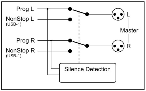
8.2 NOSTOP
The Non Stop switch is a very convenient function when you want to use your mixer while you are NON STOP on-air. By activating this switch USB channel 3 sends its signal directly to the master Cinch outputs, making your mixer completely free for production. Two Trimmers are available to even out any level differences between Non Stop mode and On-Air mode to make a convenient switch between these two modes.
8.3 WAYA
The phones output (located on the front panel) automatically switches between Main Program outputs and CUE from any input module or from the Master section. Normally the left/right output is heard until a Cue switch is activated from anywhere in the console. By pressing a CUE switch, you will hear the associated signal rather than the left/right signal in the PHONES. The software meter application switches accordingly with this action.
We advise you to use headphones with an input impedance NO LOWER THAN 2 Ohms to avoid mismatch or distortion. An 8-32 Ohm set of headphones will produce distortion when cranking up the level of the Webstation too high due to the fact that the impedance load is too low. If you must use 8-32 ohm phones, a small power amp should be used to power the phones. It is a load equivalent to the load that loudspeakers normally present to power amps. The Webstation has no power-amp gina ciki, hakuri.
8.4 CUE RESET
The Cue reset button alongside of the Phones volume control resets all active Cue selections in one go. So you do not have to switch them off individually.
8.5 CRM SECTION (Control Room Monitor)
The CRM control is normally fed by the master outputs. In case a CUE switch is activated the CRM output switches automatically to the selected CUE signal. In case you do not want the CRM output to be switched automatically to CUE disengage this function by deactivating the Auto Cue. The CRM signal can also be used for an extra stereo output for recording or a sound system.
mic channel’s CUE and the caller’s CUE and now both can talk with each other. The Talkback level can be adjusted by the TB level control just below the Non-Stop switch.
8.6 METERING
Part of the total Webstation package is a software meter application and clock as seen below.
All data is transported over the single USB 2.0 connection. An accurate clock time is taken from the local PC.
The left stereo meter always shows the Master output, the right stereo meter shows the CRM output level following every signal selected by the CUE switches.
On the right hand side of the display you see signalling functions of some important functions in this mixer.
When the ON-AIR 1 or 2 sign is activated. The NON-STOP switch is active when a Silence is detected in the program signal, a Mic is on(active) or the the CRM is muted.
On the bottom of this display you can monitor the status of all the input channels; whether they are active, off or standby and also if the source is selected.

MALAMAI BACKPANEL CONNECTORS
The master connector panel houses 12 RCA/Cinch connectors, 2 jack sockets, 3 male XLR connectors and 2x USB connector.
There is one power supply connectors. From left to right we will describe the functions and features of the master connector panel as seen below in detail.

MAI HADA WUTA
This Euro connector accepts an AC voltage in between 85 volts and 260 volts at 50/60Hz.
9.1 CRM SEND
The CRM (Control Room Monitor) outputs are on two RCA Cinch connectors carrying the signal coming from the CRM volume potentiometer on the front panel and its associated source selection. The level is 0 dBu (0.775 volt).
You can connect the inputs of active monitors to these Cinch connectors.
9.2 MASTER (SEND)
The PROG (Program) outputs are on two RCA Cinch connectors. This is also the case when the NON STOP ON-AIR switch is activated. Then these main Cinch connectors carry the USB-3 signal.
9.3 MIC ON
Directly beneath the MASTER cinch connectors is a stereo jack socket (Mic On) that can control a red light indicator.
This stereo jack is connected to an OPTO-FET. This FET switch is capable of controlling external Red light circuits as long as it doesn’t take a higher voltage than 24 volt and the current doesn’t exceed 50 mA!
KADA KA HADA 115/230 AC VolTAGE TO WANNAN JACK!!
Start / Mic-On Jack

| Functions Opto coupler | |
| Tukwici | Connected to opto-coupler |
| Zobe | Connected to opto-coupler |
| Hannun hannu | Ba a haɗa |
Our D&R ON-AIR warning light can be connected directly to the MIC-ON jack socket be-tween tip and ring by way of a simple 2 wire connection, see the manual of the ON-AIR light. The ON-AIR led light has its own external 12volt DC power adapter.
Below you see a circuit for ON-AIR lights that need AC power.

MULKIN TSAFARKI 1-2

- Haɗa wutar lantarki -amp, recorder, or transmitter to the Master left/right main outputs.
- Connect a high impedance (NOT BELOW 32 Ohm) headphone to the “phones” jack socket on the master section.
- Connect a microphone or line level equipment.
- Now, connect turntables (with built in RIAA pre-amps), CD players, and jingle machines.
- Connect a red light indicator to the master section’s Mic On jack when there is a need for it.
- Yanzu tare da duk abin da aka haɗa, bi hanyar daidaitawa.
- Note; for mikes, only activate the grey Mic switch, for line level, leave this switch up.
- Saka belun kunne kuma kunna ikon sarrafa ƙarar lasifikan kai zuwa matsayin “karfe 12”.
- Set all the gain-controls to its minimum.
- Saita duk masu sarrafa-daidaita zuwa matsayi "karfe 12".
- Connect your mains power cable and switch the console on, on the back panel.
- All switches will light for a short moment and the NON STOP will stay on.
10.1 SETTING UP AN INPUT CHANNEL
Push the CUE switch in a channel that is connected to a source. Now slowly turn the GAIN control clockwise until you hear and see the input signal on the Screen metering on your TFT display.
You can change the input sound by adjusting the equalizer-section. If you adjust the equalization, once again check the level on the meters, because increasing specific parts of the frequency spectrum can easily add more gain to the signal.
The meter indication should be between -6 dB and +3 dB to get a proper level on amplifiers or your main out processor. The screen metering is a PPM meter indicating the absolute level that enters the console. It is calibrated to indicate 0 dB on the scale corresponding with a 0 dBu output level. Release the CUE switch so the metering can now read the output signal again.
Now push the ON button to connect the input signal to the fader.
Now move the fader to the “10” position screened alongside the channel faders or to the 0dB indicator if you have cancelled the extra 10dB fader gain in the software. Further volume adjustments can be made on the equipment your signal is send to, such as power-amps or transmitters. The other inputs are similarly adjusted, using the “CUE” switches to (pre fade) listen to the connected sources.
Use the input gain for regular gain adjustments to create a convenient gain range to work with.
Be carefully not to place the Webstation near heavy power transformers such as in power amps.
Ko da yake Webstation is constructed using a thick metal frame, this could cause hum.
KAFA KYAUTA NA USB
Input modules 3 to 5 are also capable of accepting stereo USB signals from a PC where you have play-out software running.
To be able to set up a connection with your PC, use a standard USB cable as supplied by us (See picture).

Lokacin haɗawa da Webstation to your computer, the computer (PC or Mac) will recognize the Webstation as new hardware and will establish a connection to any audio programs needing audio hardware. Also all 3 stereo channels will be automatically put in a natural sequence of 1 to 3.
After establishing a connection, there is no need to down-load drivers or perform complicated setup routines.
Just plug in the USB cable to your Windows or Mac computer and start tracking/playing!
Idan kuna son ƙarin sani game da USB gwada wannan hanyar haɗin yanar gizon http://en.wikipedia.org/wiki/Audio_Stream_Input/Output
If you are already familiar with digital audio recording/processing, the latest versions of Kristal Audio Engine and Audacity are available free of charge via the Internet.
Use this link for third party downloads: https://www.asio4all.org/
SET-UP ROUTINES MODULE 6 (VoIP)

If you have already connected the USB cable for your play-out software, the VoIP connection is also available. Install for instance SKYPE on you PC and set up an account according to the instructions of the SKYPE software.
Once the dialed person has taken the call or you have answered the call, inside the SKYPE application you can talk to him via the CUE switches or make a connection outside the broadcast by first pushing the Conn switch and then pushing both the CUE switch of your DJ channel and the VoIP channel.
If you want someone else to talk to him or her prior to the broadcast push any CUE button and communication is established.
As a start, position both VoIP send and gain potentiometers in the 12 o’clock positions. Adjust when needed. An incoming call is picked up by pushing the CONN button. If you want to hear the caller, press the CUE button in the same channel to listen to the incoming call. Adjust the Gain control to get a good input level from the telephone line. To be able to talk to the caller press CUE in your DJ channel. Adjust the VoIP send potentiometer to increase or decrease the outgoing level to the caller.
Lura: This is all happening outside the broadcast.
If all is OK and both parties know what to do, you can press the ON switch and fade up the caller OnAir, or, put the fader in its “0 or 10” position and activate the ON switch to put the caller on-air.
If you do not have access to the internet and want to establish a classic connection over the telephone carrier connect a telephone Hybrid between the Cleanfeed send and Cinch sockets and the stereo line cinch inputs of the VoIP channel. Both stereo line input cinch sockets need to be feeded with the same signal.
Both cleanfeed cinch sockets carry the same mono signal, which is also send to the VoIP channel 6.

WEBSTATION CONFIGURATION MANAGER
![]()
Manajan Kanfigareshan

Manual mai amfani
KYAUTA 1.0.790.0
12.1 Gabatarwa
Webstation Configuration Manager is a software tool to configure the Webstation console.
This manual describes the features Webstation Configuration Manager contains and how to setup and use the application.
12.2 Connection & Setup
Webstation Configuration Manager communicates indirectly with the Webstation console over an Ethernet connection using UDP/IP (User Datagram Protocol). Since the only available physical communication interface on the Webstation console is USB, another Webstation Control application is required to run on the PC the Webstation is connected to (main PC).The Webstation Control acts as a USB/UDP gateway and provides a communication interface for client applications anywhere on the network, like Webstation Configuration Manager.
Don amfani Webstation Configuration Manager follow the steps below:
- Connect the USB-main port of the Webstation to your PC with the supplied USB cable
- Install, configure and run the Webstation Control application on this ‘main’ PC
- Gudu Webstation Configuration Manager on any PC in the network, or from your home!
12.3 Sadarwa
Pressing Options->Communication from the menu bar will open the communication settings window.
12.3.1 Remote Host

In the Remote Host field the IP address of the main PC needs to be specified. For running the Webstation Configuration Manager on the main PC one can use the 127.0.0.1 (localhost) IP address.
12.3.2 Tashoshi
Webstation Configuration Manager uses a transmit and receive port for the communication to/from the Webstation console. By default these ports are pre-configured and do not need to be changed unless specific port configuration is required.
12.4 Saitunan Module
In this chapter the module settings for the six modules within the console are discussed.
Each module has its own settings tab.

12.4.1 Power ON Active
The Webstation console contains ON-switches to activate a specific module.
If ON Active in the Power section is enabled the module will be active when powering the console. Using this function while a power outage occurs prevents silence on air if no person is in the studio to (re-)activate the module.

12.4.2 Auto CUE Reset
When the CUE-switch of a module in the console is activated (also called PFL) the selected source (LINE or MIC/USB/VoIP) will be routed to the CUE buss. To deactivate a module from the CUE buss you can press again the CUE-switch.
The Auto CUE Reset feature can reset the CUE buss (deactivate all modules from the CUE buss) automatically by Fader, ON and/ or Fader+ON. The function can be enabled for LINE and MIC/USB/VoIP separately.
12.4.3 On Air Busses
Two logical on-air busses are available which can be enabled for LINE and/or MIC/USB/VoIP for each module.
12.4.4 Switch Colors
In the Switch Colors section the colors of the ON and CUE switches can be configured to be OFF, RED, or GREEN depending on the state of the switch-function. It is up to the user to define a suitable color for a corresponding state.
ON states:
- ON Active
- ON and Fader Active
- ON Inactive
ON states:
- ON Active
- ON and Fader Active
- ON Inactive
12.4.5 CRM Feedback Prevention
** These settings are only available for modules 1 and 2 (MIC modules) **
In order to prevent feedback from a microphone in the Control Room the functions CRM Mute and CRM Auto Cue – (AutoDeactivate) can be enabled.
CRM Mute:
- Mute CRM buss when the module is active (MIC selected).
CRM Auto Cue – (AutoDeactivate)
- Deactivate the Auto Cue CRM function when cue’ing module (MIC selected).
12.4.6 Microphone
** These settings are only available for modules 1 and 2 (MIC modules) **
Phantom enables +48V power on the MIC XLR-connector required for condenser microphones.
MIC at Line – set this option if a microphone is connected at the line input (using external preamp).
12.5 MASTER SETTINGS
In this chapter the master settings of the console will be discussed.

12.5.1 Silence Detection
The Webstation console is equipped with a software silence detection unit which is used to monitor the program buss (left, right , stereo) in the event of the signal going below the threshold (-40…0dB) after a given interval. In this situation the unit will go into ALARM state and switches the nonstop source to the master output. The Interval Unit can be set to seconds or minutes.
The red flashing nonstop switch on the console indicates the alarm state. The silence alarm can be reset by pressing the nonstop switch (which will become green). The Program buss is routed to the master output after the reset.
12.6 Read/Write Configuration from/to console
To read the configuration from the console into the Webstation Configuration Manager you need to press the ‘READ’ button.
After the configuration has been read the firmware field shows the current firmware in the console after the read command.
Once the configuration is read successfully, adjustments can be made and written back to the console or saved as a preset.

Pressing the ‘WRITE’ button uploads the current configuration in Webstation Configuration Manager to the console. The configuration is directly active but not saved internally. The configuration is lost after a power off.
12.6.1 Store Internal
The Store Internal button stores the current configuration in the console to persistent memory (EEPROM). This means the configuration is still active after a power off. A warning will be prompted to make sure you want to overwrite the internal saved configuration.
12.7 Configuration Presets
Webstation Configuration Manager is able to import/export the configuration from/to a preset file. These preset files have the .xml file extension. A preset file includes the module and master settings.
12.7.1 Create Preset
Saving a preset can be done by pressing File->Save(as) from the menu bar.
12.7.2 Load Preset
Loading a preset can be done by pressing File->Open from the menu bar and selecting the preset file.
WEBSTATION METERS
![]()
Mita

Manual mai amfani
KYAUTA 1.1.205.0
13.1 Gabatarwa
Webstation Meters is a software tool that lets you as a user monitor and control the Webstation console in an intuitive and user friendly manner. This manual describes the features Webstation Meters contains and how to setup and use the application.

Software elements
13.1.1 Analog and Digital clock
Webstation meters provides an analog as well as a digital clock which display PC system time the application is running on. The analog clock contains a seconds dot counter which can be used as indicator for program end time countdown.
13.1.2 PPM meters
Two stereo PPM (Peak-Program-Meters) meters provide real-time and accurate readings of the Master- and CRM(Control Room Monitor) buss audio levels. A variety of PPM meter scales exist these days with all different ranges and read outs. Based on the most used scale the following type is used: IEC 60268-10 Type I, DIN scale. This scale ranges from -50 to +5dB.
13.1.3 Silence detection
Since continuous radio is important for a radio station, the Webstation is equipped with a built-in software silence detector which guards presence of audio signal on the master output. If no sound is present for a specified time, the console generates an alarm and switches automatically to non-stop mode. When the silence detector is active red line marks in the master PPM bars indicate the threshold as well as the operating mode which can be left, right or stereo.
13.1.4 MIC ON Timer
The first two modules of the Webstation can be used for connecting microphones. If one of these mic modules is active (source selector is set to mic, ON is active and fader is up) the MIC ON timer will start. Once the timer is active the elapsed time is shown in the analog clock area below the system date. The timer will reset if all the mic modules are inactive.
13.1.5 Saituna
Pressing the gear wheel symbol at the right upper corner will open the (communication) settings window.
Webstation Meters communicates indirectly with the console via a UDP/IP (User Datagram Protocol) connection. Since the only available communication interface on the webstation console is USB, another Webstation Control application is required to run on the PC the Webstation is connected to. The Webstation Control acts as a USB/UDP gateway and provides a communication interface for client applications anywhere on the network, like Webstation Meters.

13.1.6 Online indicator
Below the D&R logo the online indicator is located. This indicator will become green (online) when receiving metering data.
Tabbatar da Webstation Control application is running on the main PC in order to provide the metering data to Webstation Meters.
When the indicator shows an offline status (grey) the Webstation Control application is not running or the Webstation console is disconnected.
13.1.7 Console signals
At the right side Webstation Meters contains a set of console signals indicating internal states of the console.
PHONE : Informs you about an incoming call on module 6 (VoIP).
ON AIR 1/2 : Configurable Logical busses. Can be attached to a GPO for example.
NONSTOP : Used as indicator as well as a remote nonstop switch by clicking on the signal.
SILENCE : Indicates the silence detector is in alarm state. In this alarm state NONSTOP is flashing to indicate the console has switched automatically to nonstop mode. The alarm can be reset by clicking on NONSTOP or by pressing the nonstop switch on the console.
MIC ON : One of the mic modules is active. Behaves parallel to the hardware MIC ON output.
CRM MUTE : CRM buss is muted by active mic module where crm-mute option is enabled.
13.1.8 Module states
The Webstation console contains six modules in which their current state is represented by the rectangular icons at the bottom of the application. Each icon shows the state of the ON switch and the selected source of the relevant module.
13.1.9 ON-switch
A module can be in one of the following three states:
ACTIVE : ON active, fader down
ACTIVE_AND_FADER_ON : ON active, fader up
INACTIVE : ON inactive, fader down
Since the ON switches of the Webstation console have internal LEDs, each of the above states can be configured to represents one of the following colors: NONE, RED, GREEN. It is up to the user to determine which color represent a particular state.
The icons in Webstation Meters can be seen as duplicates of the ON switches and can therefore behave as remote of the hardware switches. Clicking on the icons results in toggling the ON state.
*** NOTE: If the icon flashes, the module is in voicetrack-mode.
13.1.10 Zaɓi tushen
Each module can select between LINE and MIC/USB/VoIP source depending on the module.
Additional to showing the ON switch state, the currently selected source for each module will be shown in the lower right corner of the icons.
13.2 Saita
Don amfani Webstation Meters follow the steps below:
- Connect the USB-main port of the Webstation to your PC with supplied USB cable
- Install, configure and run the Webstation Control application on this main PC
- Gudu Webstation Meters on any PC in the network, or from your home!

FAHIMTAR INTERNET RADIO
Daya daga cikin key fasali na Webstation is that you can set up your own Internet radio station from your home or office and have your friends listen to your broadcasts, be it music, talkshows, political, or religious programming.
Don ƙarin bayani akan Intanet, bi wannan web hanyoyin da ke ƙasa.
NOTE: D&R baya karɓar alhakin abun ciki na hanyoyin haɗin yanar gizo ko shafuka masu zuwa.
Yadda yake aiki: https://www.shoutcast.com/
Nasaraamp : https://www.winamp.com/
Shoutcast uwar garken: https://www.shoutcast.com/
Sakin da ke gaba game da Intanet na iya ba ku kyakkyawar fahimta game da rediyon Intanet.
If you wish to set up a broadcast and you are a do-it-yourself kind of person you might do well creating your own online radio station by using your own personal computer to create a dedicated server for doing the job. Some of the software options for getting this done include:
SHOUTcast:
SHOUTcast shine ainihin mafita na software na rediyo ta Intanet kyauta don yawo da sauti. Kuna iya fara tashar ku cikin sauƙi kuma software tana da kyauta don saukewa. http://www.shoutcast.com/download
Helix Server Basic
Software na sabar kafofin watsa labarai mai yawo kyauta wanda zai iya rarraba bidiyo kai tsaye da kan buƙatu da sauran kafofin watsa labarai. Realnetworks.com describes it as: “Simple 5-stream server. This free media server is a great solution if you are getting started with streaming media and want to experiment before rolling it out to a large audience.”
The Helix Server Basic is free to download. https://realnetworks.com/realplayer-page
Sabar Saurin Yawo Mai Sauri
Apple.com ya ce: "Ko kuna neman ƙara kafofin watsa labarai masu gudana zuwa ga ku web site, deliver distance learning or provide rich content for your mobile subscribers, Mac OS X Server has all of the tools you need. QuickTime Streaming Server lets you deliver live or prerecorded content in real time over the Internet.” You can find out more at apple.com. https://support.apple.com/nl-nl/guide/quicktime-player/welcome/mac
Mai Watsawa Mai Saurin Lokaci
Apple.com ya rubuta: "Hada ikon QuickTime da Apple ta sauƙi na amfani, QuickTime Broadcaster damar kawai game da kowa don samar da wani live watsa shirye-shirye taron." Zazzage wannan software daga apple.com https://www.apple.com/quicktime/broadcaster/
Mai kallo
Peercast.org is a non-profit website that provides free peer-to-peer broadcasting software. “PeerCast is a simple, free way to listen to radio and watch video on the Internet. It uses P2P technology to let anyone become a broadcaster without the costs of traditional streaming,” according to the peercast.org website. http://peercast.sourceforge.net/
Icecast
Icecast shine "software na uwar garken kyauta don yawo multimedia." Zazzage kwafi daga icecast.org. https://www.icecast.org/
BAYANIN FASAHA
15.1 BAYANI
| GABATARWA. | : Mic inputs : XLR connector balanced impedance 2 kOhm. : Pin 1 = ground. : Pin 2 = hot (in phase). : Pin 3 = cold (out of phase). : +48 volt Phantom power : bal, 2 kOhm, XLR. ,48 volt Phantom. : Noise 128 dBr (A-weighted). : Sensitivity- 70dB min, OdB Max. |
| LINE | : unbal, 10kOhm, Cinch. : Gain range of 40dB. |
| INSERTS. | : Stereo jack, -10dBv : Tip = Output (connect to input of signal processor) : Ring = Input (connect to output of signal processor) : Ground =shield |
| MAI daidaitawa | : High: + / -12 dB at 12kHz shelving. : Low: + / -12dB at 60 Hz shelving. |
| USB | : 3x Stereo in and 3x stereo out (+ and incl VoIP) : Fully compliant with USB 2.0 playback and record mode. 3x Stereo in and Main stereo, Voice Track or VoIP signal out. HID Functions: Volume|Mute|Control |
| USB CONTROL SECTION. | : 12 free assignable illuminated switches plus encoder, based on the HID protocol. |
| MIC ON | : Stereo jack, Tip is a change over contact between sleeve and ring. NOT FOR 110/220 VOLT SWITCHING!!!!!!! It can only switch 24V/50mA max! |
| FITARWA | : Left/Right + 0 dBu unbalanced on Cinch : Headphone 32-600 Ohm, Jack. : USB out can be Main program stereo signal/VoiceTrack/VoIP |
| GABA DAYA | : Frequency response: 10 – 60.000Hz. : Distortion: < 0.01% max at 1 kHz. : Start switch: isolated reed relay. (24volt/50mA) : Metering On Screen |
| SOFTWARE | : A software protocol is available for programming of the USB HID protocol to match your software. |
“We reserve the right to change or improve specifications when necessary”
15.2 GIRMA
| Hagu-Dama | ku: 350 mm |
| Gaba-Baya | ku: 315 mm |
| Tsayi | : 30 mm to 90 mm. |
| Front panel thickness | ku: 2 mm |
| Radius Corners | ku: 20 mm |
| Nauyi | ku: 8kg. |
| Drop through hole | Girman: 320mm x 295mm |
Muna yi muku fatan shekaru masu yawa na haɓaka aiki ta amfani da wannan ingantaccen samfurin daga:
| Kamfanin | : D&R Electronica b.v. |
| Adireshi | : Rijnkade 15B |
| Lambar titi | Saukewa: 1382G |
| Garin | : WUTA |
| Ƙasa | : Netherlands |
| Waya | : 0031 (0) 294-418 014 |
| Fax | : 0031 (0) 294-416 987 |
| Website | : http://www.d-r.nl |
| Imel | : mail@dr.nl |
15.3 TAKAITACCEN
We hope this manual has given you sufficient information to use this new Webstation mixer in your studio.
Idan kana buƙatar ƙarin bayani tuntuɓi dila na gida ko aiko mana da imel a mail@dr.nl kuma za mu amsa imel ɗin ku a cikin sa'o'i 24 a cikin kwanakin mako.
Idan kun sayi wannan mahaɗin daga mai shi na baya, duba dillalin da ke yankin ku akan mu website www.dr.nl idan kuna buƙatar taimako.
15.4 JAM'IYYAR ELECTROMAGNETIC
Wannan naúrar ta yi daidai da ƙayyadaddun Samfuran da aka gani akan Bayanin Daidaitawa.
Aikin yana ƙarƙashin sharuɗɗa biyu masu zuwa:
Wannan na'urar bazai haifar da tsangwama mai cutarwa ba
This device must accept any interference received, including interference that may cause undesired operation Operation of this unit within significant electromagnetic fields should be avoided. Use only shielded interconnecting cables.
15.5 BAYYANA GASKIYA
| Name Manufacturer | : D&R Electronica b.v. |
| Address manufacturer | : Rijnkade 15b, : 1382 GS Weesp : Netherlands |
ya bayyana cewa wannan samfurin
| Name product | : webtasha |
| Lambar samfurin | :na ba |
| Product options installed | : babu |
passed the following product specifications
| Tsaro | : IEC 60065 (7th ed. 2001) |
| EMC | : EN 55013 (2001+A1) EN 55020 (1998) |
Ƙarin Bayani:
Samfurin ya wuce ƙayyadaddun ƙa'idodi masu zuwa;
: Ƙara girmatage 72/23 / EEC
EMC-Direkta 89/336 / EEC. kamar yadda aka gyara ta Hanyar 93/68/EEC
(*) Ana gwada samfurin a cikin yanayin mai amfani na yau da kullun.
15.6 KYAUTATA KYAUTA
An kera wannan samfurin tare da mafi girman ma'auni kuma an duba shi sau biyu a sashin kula da ingancin mu don dogaro a cikin “HIGH VOLTAGE” sashe.
15.7 HANKALI
Never remove any panels, or open this equipment. No user serviceable parts inside.
Equipment power supply must be grounded at all times. Only use this product as described in the user manual or brochure. Do not operate this equipment in high humidity or expose it to water or other liquids. Check the AC power supply cable to assure secure contact. Have your equipment checked yearly by a qualified dealer service center. Hazardous electrical shock can be avoided by carefully following the above rules.
Ƙasa duk kayan aiki ta amfani da fil ɗin ƙasa a cikin kebul na samar da wutar lantarki. Kar a taɓa cire wannan fil.
Dole ne a kawar da madaukai na ƙasa kawai ta hanyar amfani da keɓancewa ga duk abubuwan shigarwa da abubuwan da aka fitar.
Sauya duk wani busa fiusi da nau'in iri ɗaya da ƙima kawai bayan an cire haɗin kayan aiki daga wutar AC. Idan matsala ta ci gaba, mayar da kayan aiki ga ƙwararren ƙwararren sabis.
Hum madaukai ya kamata a warke kawai ta hanyar ingantattun wayoyi da keɓewar shigarwa/fitarwa tafsiri.
Sauya fis ɗin koyaushe da nau'in iri ɗaya da ƙima bayan an kashe kayan aiki da cire su.
Idan fis ɗin ya sake busa kuna da gazawar kayan aiki, kar a sake amfani da shi kuma mayar da shi ga dilan ku don gyarawa.
Koyaushe kiyaye bayanin da ke sama a zuciyarsa lokacin amfani da kayan aikin lantarki.

feels good, does more
![]()
D&R Electronica B.V. | Rijnkade 15b | 1382GS Weesp | Netherlands
Phone: +31 (0)294-418014 | Website: https://www.dnrbroadcast.com | Imel: sales@dr.nl
Takardu / Albarkatu
 |
DR WebManajan Kanfigareshan Tasha Software [pdf] Manual mai amfani Webstation Configuration Manager Software, Configuration Manager Software, Manager Software, Software |