devolo MultiNode LAN Networking For Billing and Load Management

Product Information
Specifications
- Product: devolo MultiNode LAN
- Version: 1.0_09/24
- Powerline-based communication device
- Overvoltage category: 3
- For fixed installation on a DIN rail
- Intended for water-protected environments
Product Usage Instructions
Chapter 1: Product Documentation and Intended Use
Ensure that you have all the necessary supplied documents including safety & service flyer, data sheet, user manual for devolo MultiNode LAN, user manual for MultiNode Manager, and installation manual.
Follow the instructions carefully to prevent damage and injury.
Chapter 2: Specifications of devolo MultiNode LAN
The MultiNode LAN is a Powerline-based communication device suitable for operation in water-protected environments. It is designed for fixed installation on a DIN rail in touch-protected or access-controlled areas.
Chapter 4: Electrical Installation
Refer to chapter 4 for safety notes and detailed instructions on mounting and electrical installation of the MultiNode LAN.
Chapter 5: MultiNode LAN Web Interface
Learn how to configure your network using the built-in web interface of the MultiNode LAN by following the instructions provided in this chapter.
Frequently Asked Questions (FAQ)
- Q: Can the MultiNode LAN be used in outdoor environments?
- A: The MultiNode LAN is designed for operation in water-protected environments. It is recommended for indoor use or in environments where it is protected from outdoor elements.
- Q: Is professional installation required for setting up the MultiNode LAN?
- A: Yes, the installation, setup, and attachment of power supply lines should be performed by qualified electrical engineering personnel in compliance with relevant standards to ensure proper functioning and safety.
Notes
Please read all instructions carefully before initial use of the device. Store this user manual, the Multi-Node Manager user manual as well as the safety & service flyer for future reference.
Please note that the installation, set up, commissioning and attachment of power supply lines to the devices may be performed by qualified electrical engineering personnel only in accordance with MOCoPA and other relevant standards
Product documentation
This user manual is one part of a product documentation consisting of the following supplied documents
| Document title | Description |
| Safety & service flyer | Flyer including general safety & service information |
| Data sheet | Technical specifications of the MultiNode LAN |
| User manual devolo MultiNode LAN (this document) | Installation manual (for qualified electricians) |
| User manual for devolo MultiNode Manager (see 1.2 Intended use) | User manual for MultiNode Manager, a software application that can help you setup and manage MultiNode networks |
Overview of this manual
This user manual is intended to help you to handle the product correctly and confidently. It describes the features, mounting and installation steps of the devices as well as the built-in web interface. The manual is structured as follows:
- Chapter 1 contains information of all supplied product documents, the description of the intended use, safety information and symbol description, CE information as well as a glossary of the most important technical MultiNode terms.
- Chapter 2 (see 2 devolo MultiNode LAN) presents the specification of a MultiNode LAN.
- Chapter 3 (see 3 Network architecture in EV charging infrastructures) describes typical network architectures and illustrates how MultiNode LAN products could be used in these architectures.
- Chapter 4 (see 4 Electrical installation) contains safety notes and describes the mounting and electrical installation of the MultiNode LAN.
- Chapter 5 (see 5 MultiNode LAN web interface) describes how to configure your network via the built-in MultiNode LAN web interface.
- Chapter 6 (see 6 Appendix) contains support information and our warranty terms.
Intended use
- Use the MultiNode LAN products, the MultiNode manager and the provided accessories as instructed to prevent damage and injury.
- The MultiNode LAN is a Powerline-based communication device for operation in water-protected environment. It is a device of overvoltage category 3 and for fixed installation to be mounted on a DIN rail in a touch-protected or access-controlled environment.
- The MultiNode Manager is a multi-platform software application to setup, manage and monitor MultiNode networks.
Safety
It is essential to have read and understood all safety and operating instructions (see chapter 4.1 Safety instructions) before the device is used for the first time.
About the flyer “Safety & service“
The flyer “Safety & service“ provides general product and conformity-relevant safety information (e.g. general safety notes) as well as disposal information.
A printout of the Safety & service flyer is included with each product; this user manual is provided digitally. Furthermore, all relevant product descriptions are available on the Internet at www.devolo.global/support/download/download/multinode-lan
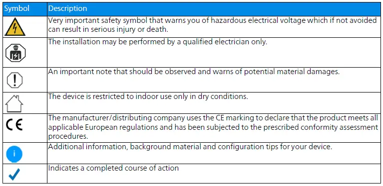
Description of symbols
This section contains a brief description of the icons used in this user manual and/or on the rating plate,
![]() CE conformity
CE conformity
A printout of the simplified CE declaration of this product is separately included. The complete CE declaration can be found under www.devolo.global/support/ce
UKCA conformity
 A printout of the simplified UKCA declaration of this product is separately included. The complete UKCA declaration can be found at www.devolo.global/support/UKCA
Glossary of technical MultiNode terms
- PLC
Powerline Communication using the electrical wiring for data communication. - MultiNode LAN network
A MultiNode LAN network is a network established by MultiNode LAN products. - Node
A node is a device of a MultiNode network. - Master node
Only one node in a MultiNode network can be the master node. The master node acts a controller of the other nodes in the network. - Regular node
In a MultiNode network, every node except the master node is a regular node. Regular nodes are controlled by the master node. - Repeater node
A repeater node is a regular node in a MultiNode network with repeater functionality. - Leaf node
A leaf node is a regular node in a MultiNode network without repeater functionality. - Seed
Seed is an identifier of a PLC-based network (integer within range 0 to 59) that is used to separate traffic between different PLC-based network.
Devolo MultiNode LAN
The devolo MultiNode LAN (named MultiNode LAN in this document) communicates via electrical wiring and enables Ethernet transport over mains low voltage cables. It is well suited to support power line communication (PLC) networks with a high number of network nodes. Its repeating functionality allows to span network domains of larger extent.
Specification
The MultiNode LAN consists of
- Five line connections
- One Gigabit network interface
- Three indicator lights
- Power
- Network
- Ethernet
- One reboot button
- One factory reset button
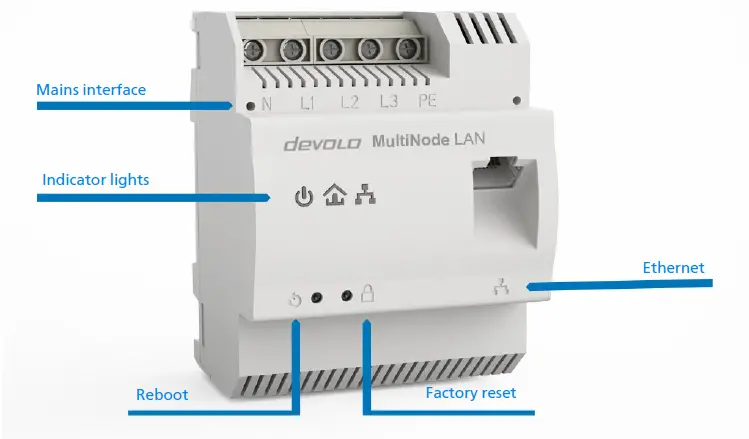
Fig.1
Mains interface
The screw terminals for connection to the primary voltage power line accept wires of gauge in the range from 1.5mm2 to 6mm2.
Single-phase operation using L1
If the device is used for single phase operations, the L1 terminal must be used. L2 and L3 can be left open. As the device is only powered from L1/N, the use of terminal L1/N is mandatory.
Three-phase connection
The neutral conductor and three external conductors are connected to the terminals N, L1, L2 and L3. The device is supplied with power via terminals N and L1.
PE connection
Operation with or without protective earth (PE)
The device can be operated without PE terminal being connected to protective earth. The PE terminal is used not for protective purpose, but for enhanced signal transmission over powerline. Nevertheless the use of PE is optional.
Ethernet interface
You can use the Ethernet interface (Fig. 1) on the MultiNode LAN to connect
- the master node to the local network or to an internet gateway or
- all other nodes (which are regular nodes) to their corresponding application devices (e.g. EV charging stations).
Indicator lights
The integrated indicator lights (LED) show the status of the MultiNode LAN by illuminating and/or flashing in three different colours:
| LED | Behaviour | Status | LED status display (web interface*) |
| Off | No power supply or defective node. | Cannot be disabled | |
| On | Node has power turned on. | Can be disabled | |
| Lights up red for 5 sec. | Node is starting up after a reboot or power cycle. | Cannot be disabled | |
| Lights up steady red | Node is unconnected to a MultiNode network and is ready to be configured. | Can be disabled | |
| Lights up steady white | Node is connected to a MultiNode network | Can be disabled | |
| Flashes white at intervals of 1.8 sec. on and 0.2 sec. off | Node is connected to a MultiNode network but the configuration is incomplete. See chapter 5
MultiNode LAN web interface for configuration instructions. |
Can be disabled | |
| Flashes at intervals of 1.9 sec. white and 0.1 sec red | Node is connected to a MultiNode network but has a poor connection. | Can be disabled | |
| Flashes at intervals of 0.3 sec. white and 0.3 sec red | Firmware update is in progress | Cannot be disabled | |
| Flashes red at intervals of 0.5 sec. (on/off) | Factory reset is successful | Cannot be disabled |
| LED | Behaviour | Status | LED status display (web interface*) |
 Ethernet Ethernet |
Lights up steady white | Ethernet uplink is active. | Can be disabled |
| Flashes white | Ethernet uplink is active and data transmission. | Can be disabled |
Factory reset button
 Resetting a MultiNode LAN to factory default
To restore a MultiNode LAN to factory default configuraton, press and hold the factory reset button longer than 10 seconds. If the node was part of a MultiNode network, it will now be removed from this network.
Wait until the network LED![]() flashes red and integrate the MultiNode LAN into another network; proceed as described in chapter 5.4.2 Adding a new node to an existing MultiNode network. Note that all settings will be lost!
flashes red and integrate the MultiNode LAN into another network; proceed as described in chapter 5.4.2 Adding a new node to an existing MultiNode network. Note that all settings will be lost!
Reboot button
![]() Rebooting a MultiNode LAN
Rebooting a MultiNode LAN
To reboot a MultiNode LAN press the reboot button. Your MultiNode LAN will now reboot. As soon as the network LED![]() lights up red your MultiNode LAN is again operational.
lights up red your MultiNode LAN is again operational.
Network architecture in EV charging infrastructures
- If you plan to use MultiNode products in EV charging infrastructures, this chapter provides our recommended network architectures for various charging setups, and highlights common pitfalls to avoid. If your use of MultiNode products for a different purpose, you may skip this chapter.
- Powerline communication (PLC) technology is well suited to support the communication needs in car parks with multiple charging stations.
- Car parks are typically equipped with power rails, which provide a powerful and efficient backbone for power distribution. PLC technology can make use of this backbone to reduce cabling efforts, e.g. with Ethernet. PLC technology also supports gradual expansion of charging stations, which is typical in car park charging infrastructure.
- On this page, we outline our recommendations for possible network architectures in car parks as well as potential pitfalls. The choice of network architecture should be made before physical installation of MultiNode LANs.
Chapter structuring
- Network architecture in charging infrastructures
- Multi-floor coverage
- Conclusion
Network architecture in charging infrastructures
There are two types of installations based on the charging infrastructures
- Type A installation: Charging stations are managed by a dedicated management entity; this is typical in larger installations.
- Type B installation: One of the charging stations acts as the management entity (i.e. the master) and the other “regular” charging stations are controlled by this entity; this is typical in smaller installations.
Peer-to-peer isolation
An important characteristic of MultiNode networks is peer-to-peer isolation. This means that a leaf or repeater node cannot communicate with other leaf or repeater nodes. Communication is only possible between each leaf or repeater node and the master node via Ethernet. This property is essential for the selection of the physical network topology.
Type A installation
In Type A installations, direct communication between the charging stations is not required. The peer-to-peer-isolation in MultiNode network is therefore not a concern, as long as the dedicated manag-ment entity is reachable via the Ethernet uplink of the master node.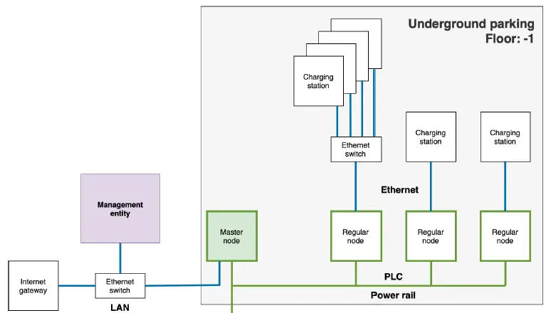
Type B installation
In Type B installations, with a master charging station and other regular charging stations controlled by it, the master charging station needs to be located on the upstream side of the MultiNode network’s master node to allow for communication with other charging stations. An additional Ethernet switch might be required to do this.
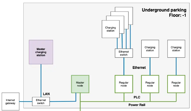
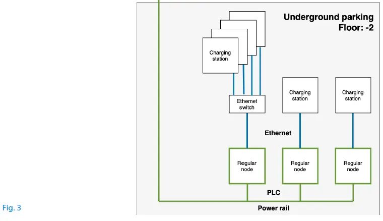
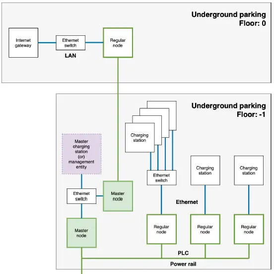
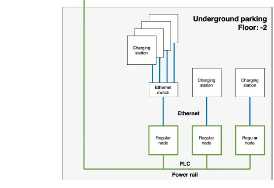
Multi-floor coverage
In typical large-scale installations, charging stations could be located across multiple floors of a car park with the internet gateway located far away from the charging stations. In such situations, do not use a single MultiNode network throughout the car park as shown below:
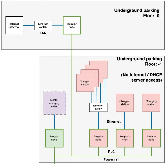
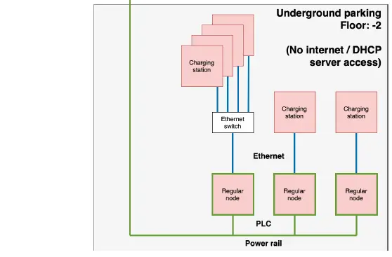
- Here, the master charging station can manage regular charging stations. However, while the master charging station can reach the DHCP server and communicate with the Internet, the regular charging stations do not have Internet access due to peer-to-peer limitation! Also, they cannot make use of a DHCP server to obtain IP addresses. For these reasons, the above non-functional network architecture must be avoided.
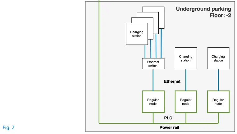
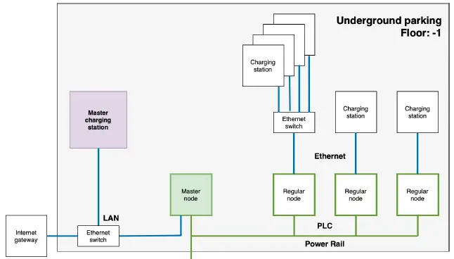
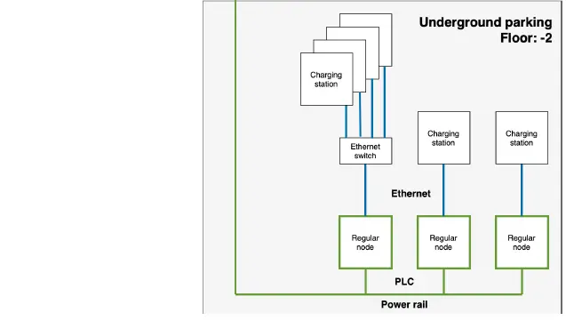
- We instead recommend using an additional MultiNode network, with the master node of this additional MultiNode network located next to the dedicated management entity in Type A installations.
Alternatively, Ethernet cabling can be used to connect several MultiNode networks across floors of the car park as shown below:
Conclusion
This document outlines our recommendations for network architecture. Do consider our recommendations and potential pitfalls carefully before physical installation of MultiNode networks.
Our recommendations also hold true for evolving installations, i.e. installations that start with a small number of charging stations in a Type B installation but extend to more charging stations or even migrate to a Type A installation.
Electrical installation
Safety instructions
All safety and operating instructions should be read and understood before using the device, and should be kept for future reference.
- For planning and installation, observe the applicable standards and directives of the respective country.
- MultiNode LAN is a device of overvoltage category 3. MultiNode LAN is a fixed installation device to be mounted on a DIN rail in a touch-protected or access-controlled environment. The device must only be operated with neutral wire!
- The work must be performed by a qualified electrician. The accepted rules of electrical engineering must be complied with including standards such as the German Energy Act § 49 and to DIN VDE 0105-100 in Germany.
- The mains supply circuit requires to be equipped with a circuit breaker in accordance with DIN VDE 100 to protect the wiring.
DANGER! Electrical shock caused by electricity or fire
Before mounting the device it is essential that the mains power supply is disconnected and se-cured against being switched on again. Observe the relevant safety regulations, otherwise there is a risk of electric shock or arcing (risk of burns). Use a suitable measuring instrument to verify the absence of hazardous voltage before work is commenced.
DANGER! Electrical shock caused by electricity or fire (incorrect conductor cross-section and improper installation of the power supply)
A sufficient conductor cross-section must be used in accordance with the dimensioning of the circuit breaker. Ensure that the power supply is correctly installed.
- Never open the device. There are no user-serviceable parts inside the device.
- Use the device in a dry location only.
- Do not insert any objects into the openings of the device.
- Ventilation slots of the housing should not be blocked.
- Protect the device from direct sunlight.
- Overheating of the device has to be avoided.
In the event of damage, contact customer service. This applies, for example, if
- liquid has been spilled on the device or objects have fallen into the device.
- the device has been exposed to rain or water.
- the device does not work, even though the operating instructions have been followed properly.
- the device’s case is damaged.
Mounting
- Turn off the mains power supply.
- Open the junction box or charging station where the MultiNode LAN shall be installed.
DANGER! Electrical shock caused by electricity! Verify the absence of hazardous voltage - Now install the new MultiNode LAN properly on the top-hat rail of the corresponding junction box or charging station. Please consider that the vertical installation alignment of the device, so that the mains power supply comes from above. The printing on the housing must be legible.
- Now connect the conductors according to the line connections. Make sure that the conductor cross-section is 1.5mm2 to 6mm2 depending on the circuit breaker rating.
- Single-phase connection: Neutral conductor and external conductor are connected to the terminals N and L1.
- Three-phase connection: Neutral conductors and three external conductors are connected to the terminals N, L1, L2 and L3. The device is supplied with power via the terminals N and L1.
- PE connection: The earth wire can be connected to the PE terminal..
- Connect the Ethernet port of the MultiNode LAN to the Ethernet interface of the corresponding application device (Internet gateway device, Ethernet switch, charging station).
We recommend documenting the MAC address, serial number and the installation location (e. g. floor and/or parking lot number) of each mounted node. The MAC address and serial number can be found on the label on the frontside of the housing.
This documentation is useful both during the initial provisioning of the network, as well as locating faulty network device later.
After completing the installation provide this documentation to the network administrator. - To set up a new MultiNode network, you need at least two nodes. Repeat the steps 2 to 5 for each node you want to install.
- After installing all devices, turn on the mains power supply and then close the junction box or charging station.
The electrical installation is now finished. If your nodes are not provisioned yet, please proceed with the configuration of your MultiNode network in the following chapter.
MultiNode LAN web interface
The MultiNode LAN provides an integrated web server. This chapter describes the network configuration using the MultiNode LAN web interface.
MultiNode Manager vs MultiNode LAN web interface
- There are two options to configure your network, using the MultiNode Manager or the built-in web interface of the MultiNode LAN device.
- If you want to operate multiple networks or a large network with five or more nodes, we recommend using the MultiNode Manager. In this case, please read the MultiNode Manager user manual for further instructions.
- It can be found at www.devolo.global/support/download/download/multinode-lan
- If you want to operate a small network with less than five nodes, you can use the MultiNode LAN web interface to setup and manage your network. The rest of this chapter provides an overview of the web interface.
Accessing the web interface using a web browser
The MultiNode LAN web interface can be accessed via web browser using the device name or the IPv4 address.
Initial access to the web interface
Serial number
The built-in MultiNode LAN web interface of a factory-default device can be accessed through its default device name devolo-xxxxx. The xxxxx are placeholders for the last 5 digits of the device‘s serial number. The serial number can be found on the label on the frontside of the housing and/or documented as described in chapter 4.2 Mounting, step 5.
- To call up the built-in MultiNode LAN web interface, use a web browser on your computing device and enter one of the following addresses (depending on the browser) in the address bar:
- devolo-xxxxx.local
- http://devolo-xxxxx.local
Please ensure that your computing device (e.g. a laptop) is connected via Ethernet to the node that you want to configure as the master node of your MultiNode LAN network.
Note: The device name is still the default name devolo-xxxxx. Once the MultiNode LAN is renamed (see chapter 5.7.2 System Management), it is no longer accessible via the default device name.
IPv4 address
There are several ways to obtain the IPv4 address of a node
- The IPv4 address is provided by your DHCP server (e. g.router). By means of the device‘s MAC address you can read out. The MAC address of the device can be found on the label on the frontside of the housing.
- The IPv4 addresses as well as the MAC addresses of all regular nodes are displayed in the Overview page of the master node’s web user interface. If the master node is still in factory defaults, its web interface can be accessed by means of the default device name devolo-xxxxx.
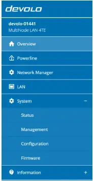
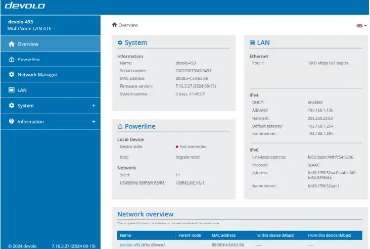
Overview
The information shown on the Overview page depends on whether the node is configured as a master or as a regular node. For a master node, its connection status (Device state) and all connected regular nodes are shown. For a regular node, while its connection status is shown, only some of the other nodes are shown due to peer-to-peer isolation.
For more information regarding to peer-to-peer isolation see chapter 3 Network architecture in EV charging infrastructures.
Overview System
Name: Node name; enables access to web interface. xxxxx are placeholders for the last 5 digits of the device‘s serial number. The serial number can be found on the label on the frontside of the housing.
For later, the node name is particularly helpful to identify and easily locate the MultiNode LAN in the network. We recommend including contextual information, e.g. parking lot number or the room in which the node is located, as a part of each node’s name. See chapter 5.7.2 System Management for instructions on renaming a node.
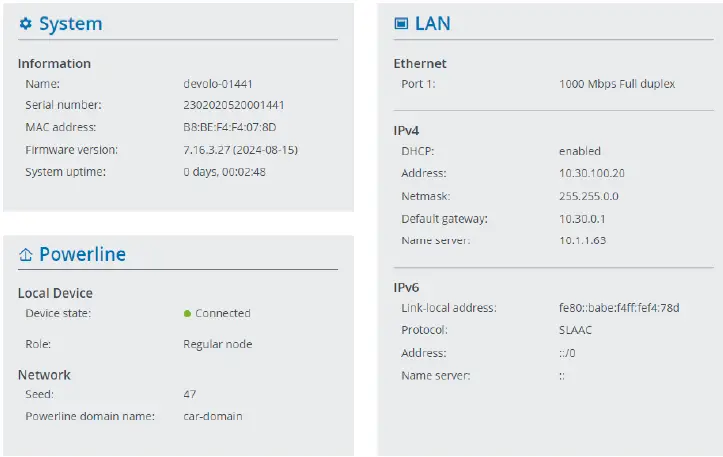
Overview Powerline
Local device
- Device state: Connection status of the node: “connected“ or “not connected“
- Role: Role of the node: “Master node“ or “Regular node“
Network
- Seed: Seed of the MultiNode network
- Connected clients: Number of nodes connected to the MultiNode network. (This is only shown on the web interface of a master node.)
Overview LAN
Ethernet
Port 1: Network connection status; if a connection has been detected, the speed (“10/100/ 1000 Mbps“) and the mode (“half/full duplex“) are specified; otherwise, the status “unconnected” is specified.
IPv4
- DHCP: DHCP status enabled or disabled
- Address: IPv4 address of the node, which can be used to access its web interface.
- Netmask: The subnet mask used in a network to separate the IP address into a network address and a device address.
- Default gateway: IP address of the router
- Name server: Address of the name server used to decode a domain name (e.g. www.devolo.global )
IPv6
- Link-local address: Selected by the device itself and is valid for the “Link-local Scope” range. The address always begins with FE80. It is used to establish connections within a local network without the need for a global IP address.
- Protocol: Address configuration protocol in use — SLAAC or DHCPv6. Under IPv6 two dynamic address configurations exist:
- StateLess Address AutoConfiguration (SLAAC)
- Stateful Address Configuration (DHCPv6)
The router (as gateway) specifies which of these two protocols is used. This is done using the M-bit in the Router Advertisement (RA) and means “Managed address configuration”. - M-Bit=0: SLAAC
- M-Bit=1: DHCPv6
- Address: Global IPv6 address used to access the Internet
- Name server: Address of the name server used to decode a domain name (e.g. www.devolo.global)
Overview Connections
For a master node, this table lists all available and connected regular nodes in your network.
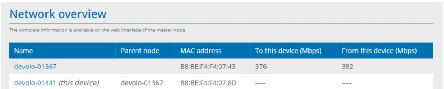
- Name: An identifier for each node in the MultiNode network
- Parent node: Identifier of the parent node. The master node has no parent; repeater nodes could have the master node or other repeater nodes as their parent; and leaf nodes
- MAC address: MAC address of the respective node
- To this device (Mbps): Data transmission rate between the node and its parent
- From this device (Mbps): Data reception rate between the node and its parent
Powerline
Setting up a new MultiNode network
Within the MultiNode network, one MultiNode LAN takes the role of the master node while all other MultiNode LANs are regular nodes – either as leaf or repeater nodes. The MultiNode network automatically decides if a regular node acts as leaf or repeater node.
In factory defaults, each MultiNode LAN is a regular node. To establish a MultiNode network, one of your MultiNode LANs has to be configured as the master node. Only this master node must be configured manually, all other regular nodes will be detected and centrally managed by the master node.
- Identify the node you want to set as the master node and open its web interface by entering either the device name or the IP address.
- Open the Powerline menu and select Master node in the Role field.
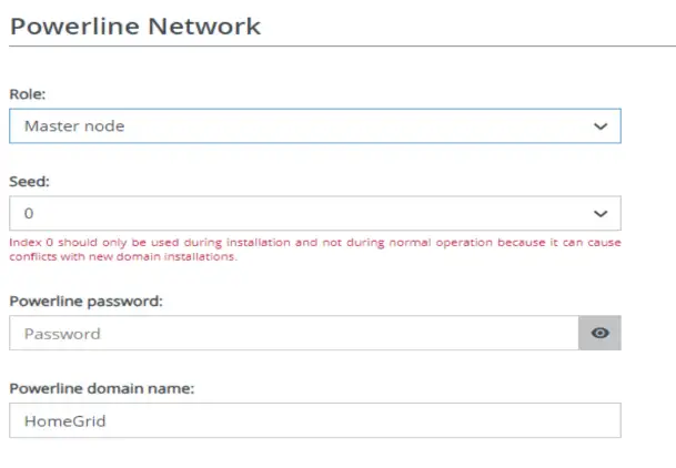
- Click the Disk icon to save the Master node setting and wait for all the expected regular nodes to join your network.
- Continue with the Network Manager menu (see also chapter 5.5 Network Manager) to customize the other Powerline parameters (seed, Powerline password and Powerline domain name) for all the nodes within your network.
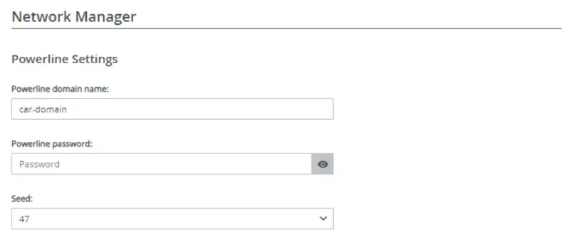 Click the Save and apply to all nodes in the domain button to save and activate the Powerline settings for the entire network.
Seed
The default value is „0“. Select a seed between 1 to 59 not already used in a MultiNode network within the installation site.
Note that the seed must be unique to each Powerline network. The default value „0“ should never be used in a live, functional network as this might affect neighboring Powerline networks.
Powerline password
Enter a network password with a maximum length of up to 12 characters and a minimum length of 3 characters. By default, the password is empty.
It is highly recommended to use a unique network password to each Powerline network within the installation site. We recommend using a password manager to store and manage passwords and other secure information about your MultiNode networks.
Powerline domain name
Enter a network name with a maximum length of up to 32 characters. The default network name is “HomeGrid”.
Note that the network name must be unique to each Powerline network. It is highly recommended to set a meaningful network name to simplify management in the long term.
Adding a new node to an existing MultiNode network
- Open the web interface of your new MultiNode LAN using the device name. Only this local node will be configured.
- Select Powerline to define the necessary parameters of the existing network:
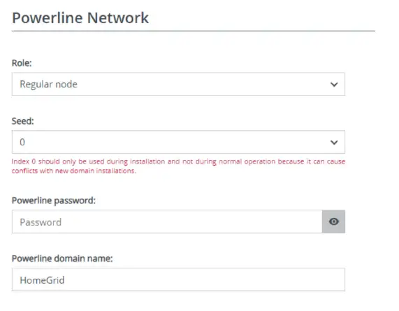
- Default is Regular node, so no changes are needed.
- Enter the settings of the existing MultiNode network in the fields Seed, Powerline password and Powerline domain name, enter the corresponding data of the existing network to which the node is to be added into.
- Click the Disk icon to save and activate the settings for the Powerline menu.
Depending on the network size, it may take some time until the new node is connected to the existing network. The house LED indicates the connection status of the node to your MultiNode network. To verify the LED and the connection status, please see the chapters 2.1.3 Indicator lights and 5.3 Overview.
Network Manager
The network manager page is only available for the master node, and can be used to edit the network parameters for all the nodes within the network.
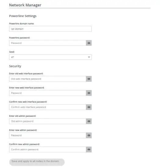
Powerline Settings
- To change the Powerline settings, edit fields Powerline domain name, Powerline password and Seed.
Security - To change the configuration password and/or admin password (required for accessing with the
MultiNode Manager), enter the old one as well as the new password twice. - Click the Save and apply to all nodes in the domain button to save and activate the settings for
LAN
Ethernet
- This menu indicates whether the Ethernet port is connected or not and lists the MAC address of the MultiNode LAN.
- You can access the web interface of the MultiNode LAN using its current IP address. This could be an IPv4 and/or IPv6 address, and is either configured manually as a static address or automatically retrie-ved from a DHCP server.
IPv4 Configuration
- In the factory default settings, only the Get IP configuration from a DHCP server option for IPv4 is enabled. This means that the IPv4 address is retrieved automatically from the DHCP server.
- If a DHCP server, e.g. Internet router is already present in the network for assigning IP addresses, you should enable the Get IP configuration from a DHCP server option so that the MultiNode LAN auto-matically receives an address from the DHCP server.
- If you want to assign a static IP address, provide details in the Address, Subnetmask, Default gateway and Name server fields.
- Confirm your settings by clicking the Disk icon and then, restart the MultiNode LAN to ensure that your changes take effect.
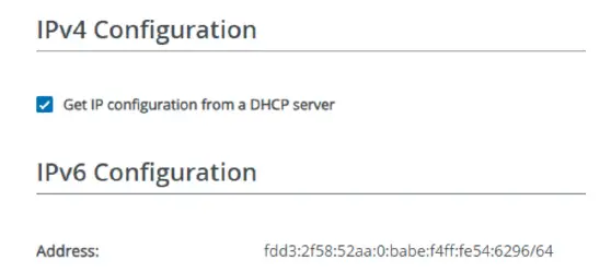
IPv6 Configuration
Address: The global IPv6 address used to access the Internet.
5.7 System
System Status
MAC address
This menu shows the MAC address of the MultiNode LAN.
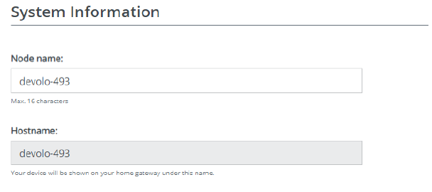
System Management
System information
System information lets you enter a user-defined name in Node name. This information is particularly helpful if a MultiNode LAN is to be identified and located in the network. We recommend including contextual information, e.g., parking lot number or the room in which the node is located, as a part of each node’s name.
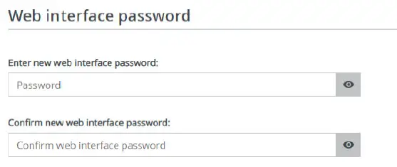
Web interface password
- By default, the built-in web interface of the MultiNode LAN is not password protected. We highly recommend setting a password after the first login to prevent unauthorised access by third parties.
- To do so, enter the new password twice.
- We recommend setting the same web interface password for all nodes in a network; to do this, set the password on the master node’s web interface.
Admin password
- The admin password is the management password used to protect the entire administration of a MultiNode LAN network.
- We highly recommend setting a new admin password after the first login to prevent unauthorised access by third parties. To do so, enter the new password twice.
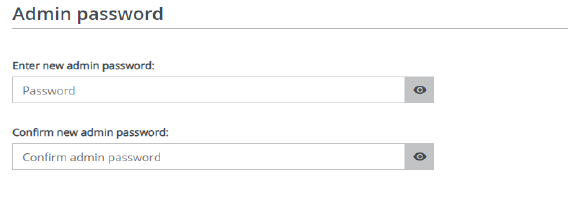
- We recommend setting the same admin password for all nodes in a network; to do this, set the password on the master node’s web interface (see chapter 5.5 Network Manager).
- It could be useful to store and manage passwords and other secure information about your MultiNode networks using a password manager.
Identify Device
The MultiNode LAN can be located using the Identify device function. Click Identify to make the white PLC LED for the corresponding adapter flash for 2 minutes to make it easier to identify by sight.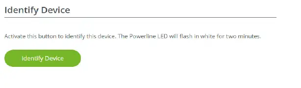
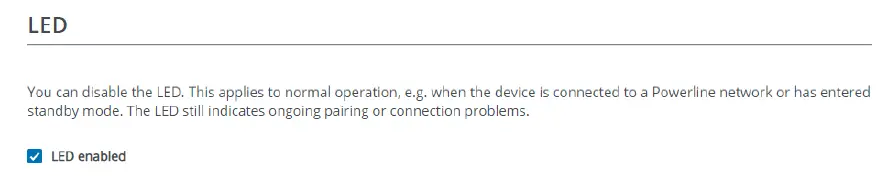
LED
Disable the LED enabled option if the LEDs on the MultiNode LAN are intended to be switched off for normal operation. An error status is indicated by corresponding flashing behaviour regardless of this setting. More information on the LED behaviour can be found in chapter 2.1.3 Indicator lights.
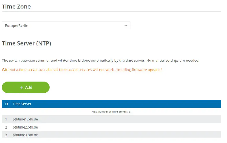
Time Zone
Under Time Zone, you can select the current time zone, e.g. Europe/Berlin.
Time Server (NTP)
The Time Server (NTP) option lets you specify an alternative time server. Using the time server, MultiNode LAN automatically switches between standard time and summer time.
System Configuration
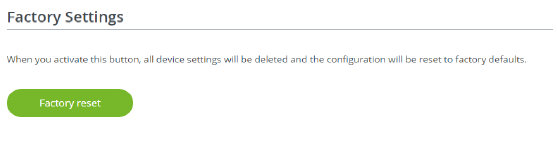
Factory Settings
- To remove a MultiNode LAN from your network and successfully restore its entire configuration to the factory default settings, click Factory reset. Note that all settings that have already been made will be lost!
- Wait until the house LED flashes red.
Reboot
In order to reboot the MultiNode LAN, click Reboot button.

System Firmware
Current Firmware
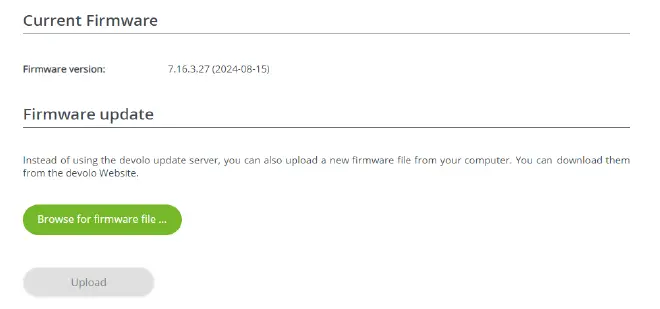
Firmware update
The web interface allows you to download the latest firmware from the devolo‘s website at www.devolo.global/support/download/download/multinode-lan to update the local node to this firmware.
To update a local node
- Select System Firmware.
- Click on Browse for firmware file… and select the downloaded firmware file.
- Continue with Upload to install the new firmware on the device. The MultiNode LAN will automatically restart. It may take a couple of minutes for the node to be available again.
Ensure that the update procedure is not interrupted. A progress bar shows the status of the firmware update.
Updating all nodes within the network
To update entire networks, use MultiNode Manager. The web interface allows to upload a file only to the local node. The user manual for MultiNode Manager can be found at www.devolo.global/support/download/download/multinode-lan .
Appendix
Contact us
More information about the devolo MultiNode LAN can be found on our website www.devolo.global . For further questions and technical issues, please contact our support via
- e-mail: support@devolo.com or
- hotline: Our hotline numbers can be found on our website www.devolo.global/support-contact
Warranty conditions
If your devolo device is found to be defective during initial installation or within the warranty period, please contact us. We will take care of the repair or warranty claim for you. The complete warranty conditions can be found at www.devolo.global/support .
Documents / Resources
 |
devolo MultiNode LAN Networking For Billing and Load Management [pdf] Owner's Manual MultiNode LAN Networking For Billing and Load Management, MultiNode LAN, Networking For Billing and Load Management, For Billing and Load Management, Load Management, Management |


