AXXESS AXDIS-FD2 Ford Data Interface With SWC
INSTALLATION GUIDE
Ford Data Interface with SWC 2011-2019
Visit AxxessInterfaces.com for more detailed information about the product and up-to-date vehicle specific applications
INTERFACE FEATURES
- Designed for non-amplified models
- Provides accessory power (12-volt 10-amp)
- Retains R.A.P. (Retained Accessory Power)
- Provides NAV outputs (parking brake, reverse, speed sense)
- Retains audio controls on the steering wheel
- Retains SYNC®
- Retains the factory AUX-IN jack
- Retains balance and fade
- Micro-B USB updatable
APPLICATIONS
FORD
Escape (w/4.3″ screen)…………………………………………………….. 2013-2019
Fiesta* (w/4.3″ screen)…………………………………………………….. 2014-2019
Focus* (w/4.2″ screen)……………………………………………………… 2012-2014**
Transit 150/250/350 (w/ AM/FM/CD)…………………………………………2015-2019
Transit Connect (w/AM/FM/CD/SYNC® radio)…………………………. 2014-2016
* Without MyFord Touch®
**For models without SYNC®, the AXSWC (sold separately) will be required to retain the audio buttons on the steering wheel.
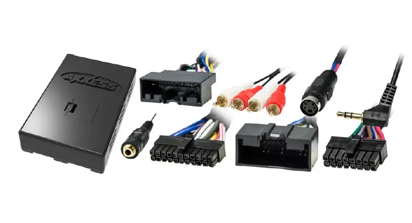
INTERFACE COMPONENTS
- AXDIS-FD2 interface
- AXDIS-FD2 harness
- 16-pin harness
- 3.5mm adapter
MetraOnline.com may be used to assist with dash assembly instructions. Simply enter your Year, Make, Model vehicle into the vehicle fit guide and look for the Dash Kit Installation Instructions.

TOOLS & INSTALLATION ACCESSORIES REQUIRED
- Crimping tool and connectors, or solder gun, solder, and heat shrink
- Tape
- Wire cutter
- Zip ties
ATTENTION: With the key out of the ignition, disconnect the negative battery terminal before installing this product. Ensure that all installation connections, especially the air bag indicator lights, are plugged in before reconnecting the battery or cycling the ignition to test this product.
NOTE: Refer also to the instructions included with the aftermarket radio.
CONNECTIONS
From the 16-pin harness to the aftermarket radio, connect the:
- Red wire to the accessory wire.
Note: If installing an AX-LCD (sold separately), there will be an accessory wire there to connect as well. - Orange/White wire to the illumination wire (if applicable).
- Brown wire to the mute wire, only if equipped with SYNC® (if applicable).
Note: If the mute wire is not connected, the radio will turn off when SYNC® is activated. - Gray wire to the right front positive speaker output.
- Gray/Black wire to the right front negative speaker output.
- White wire to the left front positive speaker output.
- White/Black wire to the left front negative speaker output.
The following (3) wires are only for multimedia/navigation radios that require these wires. - Blue/Pink wire to the VSS/speed sense wire.
- Green/Purple wire to the reverse wire.
- Light Green wire to the parking brake wire
- Tape off and disregard the following (5) wires, they will not be used in this application:
Blue/White, Green, Green/Black, Purple, Purple/Black.
From the AXDIS-FD2 harness to the aftermarket radio, connect the:
- Black wire to the ground wire.
- Yellow wire to the battery wire.
- Blue wire to the power antenna wire.
- Green wire to the left rear positive speaker output.
- Green/Black wire to the left rear negative speaker output.
- Purple wire to the right rear positive speaker output.
- Purple/Black wire to the right rear negative output.
- If the vehicle is equipped with SYNC®, connect the Red and White RCA jacks labeled “RSE/SYNC/SAT” to the audio AUX-IN jacks.
- If the vehicle is equipped without SYNC®, connect the Red and White RCA jacks labeled “FROM 3.5” to the audio AUX-IN jacks.
Note: Excluding F-150. - The DIN jack is to be used with the optional AX-LCD (sold separately) to retain SYNC® information.
- Red wire to accessory power.
3.5mm jack steering wheel control retention:
The 3.5mm jack is to be used to retain audio controls on the steering wheel.
- For the radios listed below: Connect the 3.5mm adapter to the male 3.5mm SWC jack from the AXDIS-FD2 harness. Any remaining wires tape off and disregard.
- Eclipse: Connect the steering wheel control wire, normally Brown, to the Brown/White wire of the connector. Then connect the remaining steering wheel control wire, normally Brown/White, to the Brown wire of the connector.
- Metra OE: Connect the steering wheel control Key 1 wire (Gray) to the Brown wire.
- Kenwood or select JVC with a steering wheel control wire: Connect the Blue/Yellow wire to the Brown wire.
Note: If your Kenwood radio auto detects as a JVC, manually set the radio type to Kenwood. See the instructions under changing radio type. - XITE: Connect the steering wheel control SWC-2 wire from the radio to the Brown wire.
- Parrot Asteroid Smart or Tablet: Connect the 3.5mm jack into the AXSWCH-PAR (sold separately), and then connect the 4-pin connector from the AXSWCH-PAR into the radio.
Note: The radio must be updated to rev. 2.1.4 or higher software. - Universal “2 or 3 wire” radio: Connect the steering wheel control wire, referred to as Key-A or SWC-1, to the Brown wire of the connector. Then connect the remaining steering wheel control wire, referred to as Key-B or SWC-2, to the Brown/White wire of the connector. If the radio comes with a third wire for ground, disregard this wire.
Note: After the interface has been programmed to the vehicle, refer to the manual provided with the radio for assigning the SWC buttons. Contact the radio manufacturer for more information - For all other radios: Connect the 3.5mm jack from the AXDIS-FD2 harness into the jack on the aftermarket radio designated for an external steering wheel control interface. Please refer to the aftermarket radio’s manual if in doubt as to where the 3.5mm jack goes.
INSTALLATION
With the key in the off position:
- Connect the 16-pin harness, and the AXDIS-FD2 harness, into the AXDIS-FD2 interface.
Attention! Do not connect the AXDIS-FD2 harness to the wiring harness in the vehicle just yet.
Attention! If retaining steering wheel controls, ensure that the jack/wire is connected to the radio before proceeding. If this step is skipped, the interface will need to be reset for the steering wheel controls to function.
PROGRAMMING
For the steps below, the LED located inside the interface can only be seen while active. The interface does not need to be opened to see the LED.
1. Start the vehicle.
2. Connect the AXDIS-FD2 harness to the wiring harness in the vehicle.
3. The LED will initially turn on solid Green, then turn off for a few seconds while it auto detects the radio installed.
4. The LED will then flash Red up to (24) times indicating which radio is connected to the interface, and then turn off for a couple of seconds. Pay close attention to how many Red flashes there are. This will help in troubleshooting, if need be. Refer to the LED feedback section for more information.
5. After a couple seconds the LED will turn on solid Red while the interface auto detects the vehicle. The radio will shut off at this point. This process should take 5 to 30 seconds.
6. Once the vehicle has been auto detected by the interface, the LED will turn on solid Green, and the radio will come back on, indicating programming was successful.
7. Test all functions of the installation for proper operation, before reassembling the dash. If the interface fails to function, refer to Troubleshooting section.
Note: The LED will turn on solid Green for a moment, and then turn off under normal operation after the key has been cycled.
EXTRA FEATURES
If equipped with SYNC®:
- If the vehicle is equipped with SYNC®, the AXDIS-FD2 can retain this feature.
- Change the source of the radio to AUX-IN; SYNC® audio will start playing if SYNC® has been activated.
- The display in the factory screen, or the optional AX-LCD (sold separately) will display the SYNC® information.
- Listed below are the functions of the AX-LCD while using SYNC®:
- Arrow Up—Channel up (only in USB mode)
- Arrow Down—Channel down (only in USB mode)
- Enter—Selects current item on the screen
- Return/ESC—Exits to the previous screen
STEERING WHEEL CONTROL SETTINGS
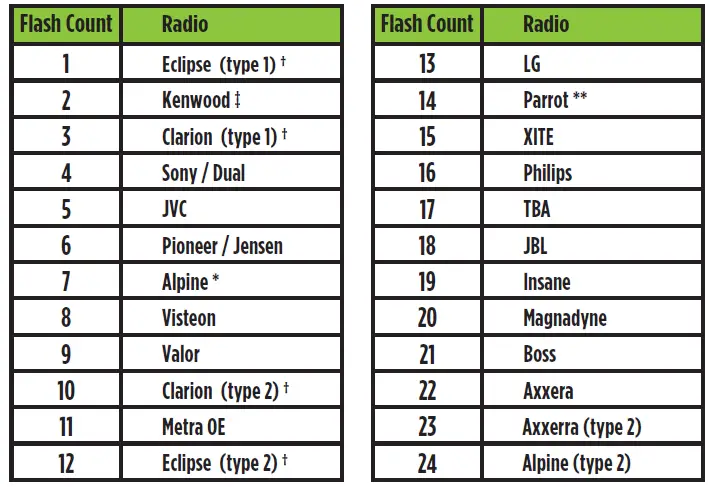
LED Feedback: The (24) Red LED flashes represent a different radio manufacturer for the AXDIS-FD2 SWC interface to detect.
For example, if you are installing a JVC radio, the AXDIS-FD2 interface will flash Red (5) times, then stop.
Following is the LED Feedback Legend, which indicates the flash count of the radio manufacturer.
LED Feedback Legend
KEYNOTES
* If the AXDIS-FD2 flashes RED (7) times, and an Alpine radio is not installed, that means there is an open connection not accounted for. Verify that the 3.5mm jack is connected to the correct steering wheel jack/wire in the radio.
** The AXSWCH-PAR is required (sold separately). Also, the software in the radio must be rev. 2.1.4 or higher.
† If a Clarion or Eclipse radio is installed and the steering wheel controls do not function, change the radio to Clarion (type 2) or Eclipse (type 2) respectively. If the steering wheel controls still do not function, refer to the Changing Radio Type document available at axxessinterfaces.com.
‡ If a Kenwood radio is installed and the LED feedback flashes (5) times instead of (2), manually change the radio type to Kenwood. To do this, refer to the Changing Radio Type document on next page, also available at axxessinterfaces.com.
Attention: The Axxess Updater App can also be used to program the following (3) sub-sections as well, pending that the interface has been initialized and programmed.
Changing Radio Type
If the LED flashes do not match the radio you have connected, you must manually program the AXDIS-FD2 to tell it which radio it is connected to.
1. After (3) seconds of turning the key on, press and hold the Volume-Down button on the steering wheel until the LED in the AXDIS-FD2 goes solid.
2. Release the Volume-Down button; the LED will go out indicating we are now in Changing Radio Type mode.
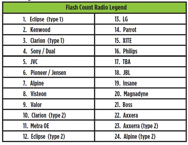
3. Refer to the Radio Legend to know which radio number you would like to have programmed.
4. Press and hold the Volume-Up button until the LED goes solid, and then release. Repeat this step for the desired radio number you have selected.
5. Once the desired radio number has been selected, press and hold the Volume-Down button on the steering wheel until the LED goes solid. The LED will remain on for about (3) seconds while it stores the new radio information.
6. Once the LED goes off, the Changing Radio Type mode will then end. You can now test the steering wheel controls.
Note: If at any time the user fails to press any button for a period longer than (10) seconds, this process will abort.
Radio Legend
Let’s say you have AXDIS-FD2 initialized and you want to change the button assignment for the steering wheel control buttons. For example, you would like Seek-Up to become Mute. Follow the steps below to remap the steering wheel control buttons:
1. Ensure the AXDIS-FD2 is visible so you can see the LED flashes to confirm button recognition.
Tip: Turning the radio off is recommended.
2. Within the first twenty seconds of turning the ignition on, press and hold the Volume-Up button on the steering wheel until the LED goes solid.
3. Release the Volume-Up button, the LED will then go out; The Volume-Up button has now been programmed.
4. Follow the list in the Button Assignment Legend to reference the order in which the steering wheel control buttons need to be programmed.
Note: If the next function on the list is not on the steering wheel, press the Volume-Up button for (1) second until the LED comes on, and then release the Volume-Up button.
This will tell the AXDIS-FD2 that this function is not available and it will move on to the next function.
5. To complete the remapping process, press and hold the Volume-Up button on the steering wheel until the LED in the AXDIS-FD2 goes out.
1. Volume-Up
2. Volume-Down
3. Seek-Up/Next
4. Seek-Down/Prev
5. Source/Mode
6. Mute
7. Preset-Up
8. Preset-Down
9. Power
10. Band
11. Play/Enter
12. PTT (Push to Talk) *
13. On-Hook *
14. Off-Hook *
15. Fan-Up **
16. Fan-Down **
17. Temp-Up **
18. Temp-Down **
* Not applicable if the vehicle is equipped with SYNC®
** Not applicable in this application
Note: Not all radios will have all of these commands. Please refer to the manual provided with the radio, or contact the radio manufacturer for specific commands recognized by that particular radio.
The AXDIS-FD2 has the capability to assign (2) functions to a single button, except Volume-Up and Volume-Down. Follow the steps below to program the button(s) to your liking.
Note: Seek-Up and Seek-Down come pre-programmed as Preset-Up and Preset-Down for a long button press.
Dual Assignment Legend
1. Not allowed
2. Not allowed
3. Seek-Up/Next
4. Seek-Down/Prev
5. Mode/Source
6. ATT/Mute
7. Preset-Up
8. Preset-Down
9. Power
10. Band
11. Play/Enter
12. PTT
13. On-Hook
14. Off-Hook
15. Fan-Up *
16. Fan-Down *
17. Temp-Up *
18. Temp-Down *
*Not applicable in this application
1. Turn on the ignition but do not start the vehicle.
2. Press and hold down the steering wheel control button that you want to assign a long press function to for about (10) seconds, or until the LED flashes rapidly. At this point release the button; the LED will then go solid.
3. Press and release the Volume-Up button the number of times corresponding to the new button number selected. Refer to the Dual Assignment Legend. The LED will flash rapidly while the Volume-Up button is being pressed, and then go back to a solid LED once released.
Dual Assignment Instructions (Long Button Press) continued from previous page
4. Go to the next step once the Volume-Up button has been pressed the desired number of times.
Caution: If more than (10) seconds elapses between pressing the Volume-Up button, this procedure will abort, and the LED will go out.
5. To store the long press button in memory, press the button that you assigned a long press button to (the button held down in Step 2). The LED will now go off indicating the new information has been stored.
Note: These steps must be repeated for each button you would like to assign a Dual Purpose feature to. To reset a button back to its default state, repeat Step 1, and then press the Volume-Down button. The LED will go out, and the long press mapping for that button will be erased.
TROUBLESHOOTING
Resetting the AXDIS-FD2
1. The Blue reset button is located inside the interface, between the two connectors.
The button is accessible outside the interface, no need to open the interface.
2. Press and hold the reset button for two seconds, and then let go to reset the interface.
3. Refer to the Programming section (page 4) from this point.
Specifications
- Product Name: AXDIS-FD2
- Compatibility: Ford Data Interface with SWC 2011-2019
- Manufacturer Website: AxxessInterfaces.com
Having difficulties? We’re here to help.
Contact our Tech Support line at:
386-257-1187
Or via email at: techsupport@metra-autosound.com
Tech Support Hours (Eastern Standard Time)
Monday – Friday: 9:00 AM – 7:00 PM
Saturday: 10:00 AM – 5:00 PM
Sunday: 10:00 AM – 4:00 PM

© COPYRIGHT 2024 METRA ELECTRONICS CORPORATION
FAQ
Q: What should I do if the LED does not turn on during programming?
A: If the LED does not turn on during programming, ensure all connections are secure and refer to the Troubleshooting section in the manual for further guidance.
Documents / Resources
 |
AXXESS AXDIS-FD2 Ford Data Interface With SWC [pdf] Installation Guide AXDIS-FD2, AXDIS-FD2 Ford Data Interface With SWC, AXDIS-FD2, Ford Data Interface With SWC, Interface With SWC, With SWC, SWC |