TTK FG-NET Leak Detection and Locating Systems


INTRODUCTION
TTK Leak Detection and Locating Systems For Indoor Design and Application Guide is mainly addressed to engineering consultants, contractors and end users. This guide, illustrated with a great quantity of drawings and diagrams, showing the TTK leak detection and locating systems as FG-NET, FG-BBOX, FG-ALS8’s typical layouts and applications in building environment.
This Design Guide with its photos, illustrations and charts was carefully prepared, but it is only intended for promotional use. TTK cannot guarantee that the information given contains no errors or omissions and will accept no responsibility related to the usage of its equipment. TTK’s only obligations are those set forth in the Standard Terms and Conditions of Sale and will not under any circumstances be held liable for any incidental, indirect or consequential damages arising from the sale, resale or misuse of this product. The purchasers are the sole judges of the product’s adaptability to the use for which it is destined. FG-NET, FG-SYS and TOPSurveillance are trademarks of TTK S.A.S. © TTK 2024
- TTK Headquarters / 19, rue du Général Foy / 75008 Paris / France / T : +33.1.56.76.90.10 / F : +33.1.55.90.62.15 / www.ttk.fr / ventes@ttk.fr
- TTK UK Ltd. / 3 Luke Street / London EC2A 4PX / United Kingdom / T : +44 207 729 6002 / F : +44 207 729 6003 / www.ttkuk.com / sales@ttkuk.com
- TTK Pte Ltd. / #09-05, Shenton House, 3 Shenton Way / Singapore 068805 / T: +65.6220.2068 / M: +65.9271.6191 / F: +65-6220.2026 / www.ttk.sg / sales@ttk.sg
- TTK Asia Ltd. / 2107-2108 Kai Tak Commercial Building / 317 Des Voeux Road Central / Hongkong / T: +852.2858.7128 / F: +852.2858.8428 / www.ttkasia.com / info@ttkasia.com
- TTK Middle East FZCO / Building 6EA, Office 510 PO Box 54925 / Dubai Airport Free Zone / UAE / T: +971 4 70 17 553 / M: +971 50 259 66 29 / www.ttkuk.com / cgalmiche@ttk.fr
- TTK Deutschland GmbH / Berner Strasse 34 / 60437 Frankfurt / Deutschland / T : +49(0)69-95005630 / F : +49(0)69-95005640 / www.ttk-gmbh.de / vertrieb@ttk-gmbh.de
- TTK North America Inc / 1730 St Laurent Boulevard Suite 800 / Ottawa, ON, K1G 5L1 / Canada / T : +1 613 566 5968 / www.ttkcanada.com / info@ttkcanada.com
PRODUCTS LIST
Belowing table lists all products you will find in this guide. For each item, a real product photo, its 3D view in drawings as well as a brief introduction are presented to ease your reading.
PRODUCTS LIST (FOLLOWING)
PART I DESIGN LAYOUTS
This part offers layout examples of locating and non-locating systems in building environment, classified by alarm unit.
General Description
Below are some technical limits of the capacity of principal control panels:
- For FG-NET, up to 40 sense cables can be connected on each circuit.
- For FG-NET-LL, up to 59 sense cables can be connected on each circuit.
- For FG-BBOX, up to 40 sense cables can be connected on each circuit.
- For FG-BBOX-LL, up to 59 sense cables can be connected on each circuit.
- For FG-SYS, up to 40 sense cables can be connected on each circuit.
- For FG-ALS8, up to 100 metres of sense cables can be connected on each circuit.
- For FG-ALS8-OD, up to 8 lengths of sense cables can be connected on the unit, no matter how the 8 cables are connected (on each zone or all in one zone).
- For FG-ALS4, up to 45 metres of sense cables can be connected on each circuit.
- For FG-ALS4-OD, up to 4 lengths of sense cables can be connected on the unit, no matter how the 4 cables are connected (on each zone or all in one zone).
- For FG-A, up to 15 metres of sense cables can be connected.
- For FG-A-OD, up to 20 metres of sense cables can be connected.
- For FG-STAD, up to 20 metres of sense cables can be connected.
Figures 1.1 Capacity of principal control panels
| Control Panels | Numbers of Integrated Circuits | Maximum Capacity Per Circuit | |
| Water & Acids Leak Detection Panels | FG-NET | 3 | 40 cables |
| FG-SYS | 3 | 40 cables | |
| FG-BBOX | 2 | 40 cables | |
| FG-ALS8 | 8 | 100 metres | |
| FG-ALS4 | 4 | 45 metres | |
| FG-A | 1 | 15 metres | |
| Hydrocarbon Leak Detection Panels | FG-NET-LL | 3 | 59 cables |
| FG-BBOX-LL | 2 | 59 cables | |
| FG-ALS8-OD | 8 | 8 cables (with no sense cables in 7 other circuits) | |
| FG-ALS4-OD | 4 | 4 cables (with no sense cables in 3 other circuits) | |
| FG-A-OD | 1 | 1 cable | |
| FG-STAD | 1 | 1 cable |
Alarm Units
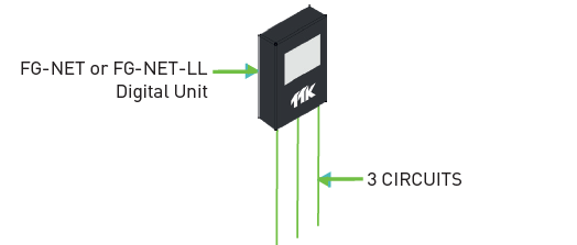
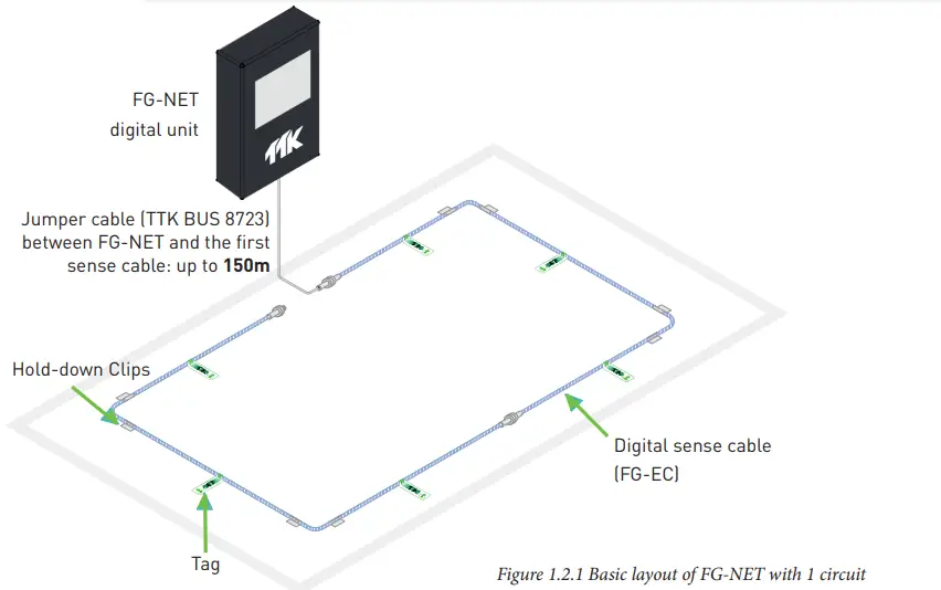
Digital Unit: FG-NET
FG-NET locating system includes basically: (figure 1.2.1)
- FG-NET digital unit.
- TTK BUS 8723 jumper cable (for connecting between panel and the first sense cables in this layout).
- Digital sense cable (FG-EC in this layout, standard lengths are 3, 7 and 15 metres).
- End termination (used at end of last sense cables, mark the termination of one circuit).
- Accessories:
- Hold-down clips (fix sense cable, stick on the floor);
- Tags (caution use).
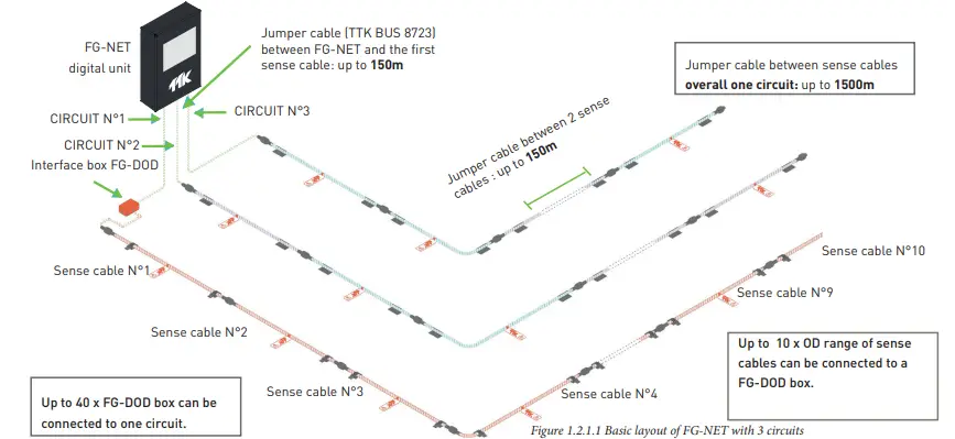
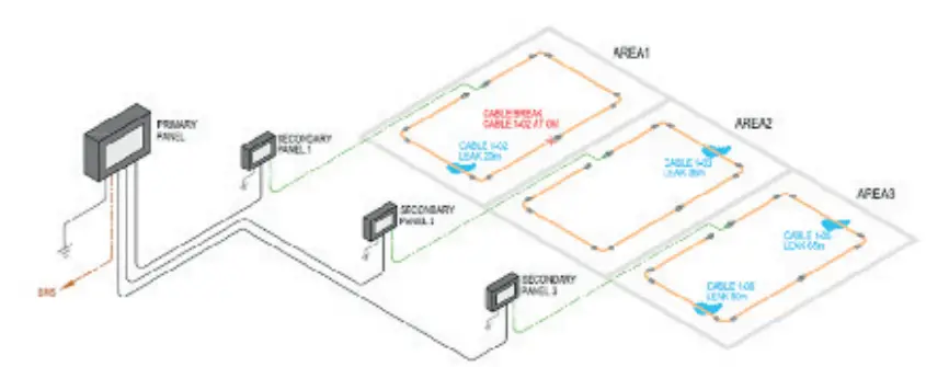
In below example of 3 circuits layout with FG-NET, there are:
- FG-NET digital unit.
- TTK BUS 8723 jumper cable:
- for connecting panel and the first water / acids sense cables for circuits 2&3;
- for connecting panel and interface box FG-DOD (explanation see 4 lines below) in circuit 1 in this layout.
- Digital sense cables:
- Water sense cables FG-EC; acids sense cables FG-AC (standard lengths are 3, 7 and 15 metres) in circuit 2 & 3;
- Hydrocarbon sense cables FG-OD (standard lengths are 3, 7, 12 and 20 metres) in circuit 1.
- Interface box FG-DOD in circuit 1: it splits TTK BUS 8723 into 2 outputs including OD BUS 8771 for FG-OD sense cable connection.
- End termination and accessories same as figure 1.2.1.
FG-NET-LL digital unit uses the same principal. It has OD BUS 8771 output. It is designed to be connected to hydrocarbon FG-OD range of sense cables / point sensors exclusively, for industry Long Line ‘LL’ applications.
For more details, ref to «TTK Fuel Leak Detection Airport / Pipeline / Storage Tank Design Guide».
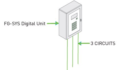
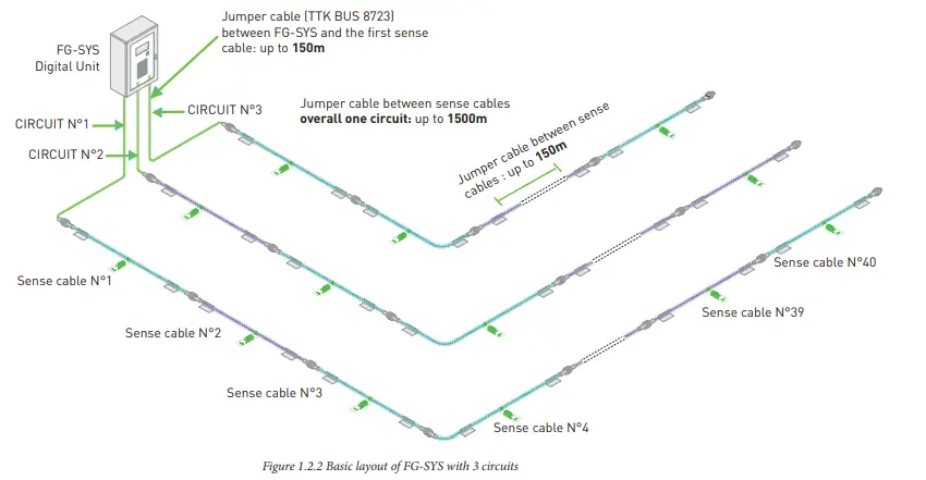
Digital Unit: FG-SYS
Concerning to design layout, FG-SYS digital unit is very similar to FG-NET digital unit, they have the same technical limit on cable lengths.
The difference is FG-SYS is designed for water and acids leak detection, thus not compatible with hydrocarbon sense cables / hydrocarbon point sensors. Water and acids sense cables can be mixed in the same circuit.
- Each circuit can connect < = 40 sense cables
- Each circuit can connect < = 600 metres of sense cables
Layout Comparison Between TTK & Other System
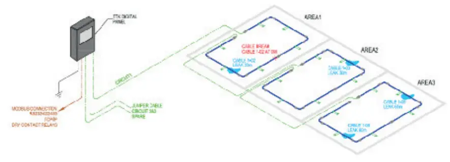
For TTK Digital System (FG-NET, FG-SYS):
- 1 sole digital panel can monitor all 3 areas, no need of any slave module.
- It detects multileaks: 4 leaks (even simultaneous) on 3 areas.
- It detects multileaks + cable break fault: 4 leaks and 1 cable break.
For Other Traditional System:
- 1 master panel + 3 slave modules are enquired to monitor all 3 areas.
- In case of multileak: only the first leak can be located precisely; others are detected but without precise location.
- In case of multileaks + cable break fault: no leak can be detected after the cable break faults in the same area.
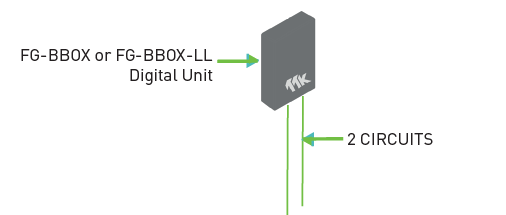
Satellite Device: FG-BBOX
- The FG-BBOX is a satellite device (or a ‘‘daughter panel’’) of the TTK FG-NET digital unit. It expands FG-NET to manage two additional circuits of sense cables with up to 1200 metres (or 80 lengths) of additional sense cables.
- FG-BBOX facilitates installation by eliminating the need to draw jumper cables between the monitoring panel and sensing cables through the building to a given area or floor thanks to its Ethernet connectivity.
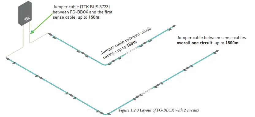
- Each circuit can connect < = 40 sense cables
- Each circuit can connect < = 600 metres of sense cables
FG-BBOX is monitored by FG-NET via a standard Ethernet network.
- In the event of a fault on the sense cables connected to the FG-BBOX, the relevant relay contact is activated and the LED on the relevant circuit switched to red.
- Each FG-BBOX proceeds TCP/IP connection via RJ45. Each FG-BBOX has four relay contacts: 2 leak relays (1 for each circuit), 1 cable break relay and 1 power failure relay.
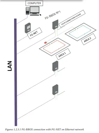
Layout Explanation (Figure 1.2.3.1) :
- FG-BBOX N°1 is connected to FG-NET via Ether-net. FG-BBOX N°1 monitors two areas: AREA 1: equipped with oil sense cable using an interface box FG-DOD (ref 1.4.5); AREA 2: equipped with water sense cable.
- Up to 16 x FG-BBOX can be connected to one FG-NET unit without exceeding a total number of 500 digital sense cables per FG-NET.
FG-BBOX-LL digital unit uses the same principal. It has OD BUS 8771 output. It is designed to be connected to hydrocarbon FG-OD range of sense cables / point sensors exclusively, for industry Long Line ‘LL’ applications.
For more details, ref to «TTK Fuel Leak Detection Airport / Pipeline / Storage Tank Design Guide».
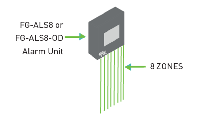
Eight Zone Alarm & Locating Unit: FG-ALS8
The FG-ALS8, eight zones alarm & locating system unit is designed to be used with analog sense cables: FG-ECS, FG-ACS or FG-ECX, FG-ACX, for water, base or acid leak detection.
In the event of liquid leak or fault on the sense cables in any zone, the FG-ALS8 will respond as follows:
- An audible alarm is triggered and a relay is activated.
- The touch screen of the panel displays the zone, the location of the leak (to the nearest metre) and details of the fault (the type of fault leak or cable break).
- Report to the BMS via MODBUS /JBUS protocol.
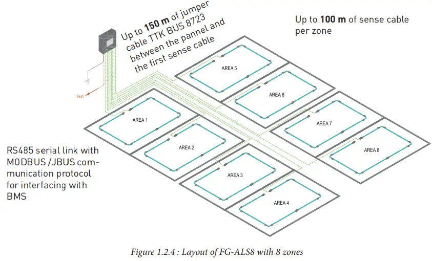
Layout Explanation (Figure 1.2.4) :
- 8 detection zones are available.
- FG-ALS8 can control up to 100m of sense cable per zone.
- In total, up to 800m of sense cable per unit.
- In case of one zone has less than 100m, the unused length can not be transferred to another zone.
Eight Zone Alarm & Locating Unit For Hydrocarbon: FG-ALS8-OD
The FG-ALS8-OD, eight zones alarm & locating system unit for hydrocarbon leak detection is designed to be used exclusively with FG-OD hydro-carbon range of detectors.
In the event of liquid leak or default on the sense cables for each zone, the responses from the FG-ALS8-OD alarm & locating unit:
- An audible alarm is triggered and a relay is activated.
- The touch screen of the panel displays the zone, the location of the leak (on the cable) and details of the fault (the type of fault leak or cable break).
- Report to the DCS/SCADA/Safeguarding system via a JBUS/MODBUS protocol.
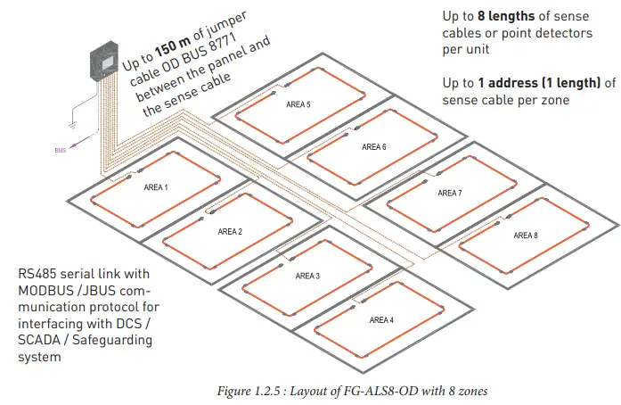
Up to 8 lengths of sense cables or point detectors per unit
Up to 1 address (1 length) of sense cable per zone
Layout Explanation (Figure 1.2.5):
- 8 detection zones are available.
- FG-ALS8-OD can control up to 1 address or 1 length (of 3, 7,12 or 20m) of sense cable or point sensor per zone.
- In total, up to 8 lengths (or 160m) of sense cables or point sensors per unit.
- Different possibilities of configurations are:
- 1 cable per zone; or
- 8 cables on the first output and leave all other seven outputs vacant, or
- other possible connection.
Point detector can be connected in the place of sense cables, see 1.3.2.
For a system with FG-ALS8 or FG-ALS8-OD unit:
- Between 2 lengths of sense cables: up to 150m of jumper cables.
- Total length of jumper cables on a unit: up to 300m.
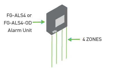
Four Zone Alarm & Locating Unit: FG-ALS4
The FG-ALS4, four zones alarm & locating system unit is designed to be used with analog sense cables: FG-ECS, FG-ACS or FG-ECX, FG-ACX, for water, base or acid leak detection.
In the event of liquid leak or fault on the sense cables in any zone, the FG-ALS4 will respond as follows:
- An audible alarm is triggered and a relay is activated.
- The touch screen of the panel displays the zone, the location of the leak (to the nearest metre) and details of the fault (the type of fault leak or cable break).
- Report to the BMS via MODBUS /JBUS protocol.
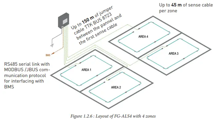
Layout Explanation (Figure 1.2.6) :
- 4 detection zones are available.
- FG-ALS4 can control up to 45m of sense cable per zone.
- In total, up to 180m of sense cable per unit.
- In case of one zone has less than 45m, the unused length can not be transferred to another zone.
Four Zone Alarm & Locating Unit For Hydrocarbon: FG-ALS4-OD
The FG-ALS4-OD, four zones alarm & locating system unit for hydrocarbon leak detection is designed to be used exclusively with FG-OD hydro-carbon range of detectors.
In the event of liquid leak or default on the sense cables for each zone, the responses from the FG-ALS4-OD alarm & locating unit:
- An audible alarm is triggered and a relay is activated.
- The touch screen of the panel displays the zone, the location of the leak (on the cable) and details of the fault (the type of fault leak or cable break).
- Report to the DCS/SCADA/Safeguarding system via a JBUS/MODBUS protocol.
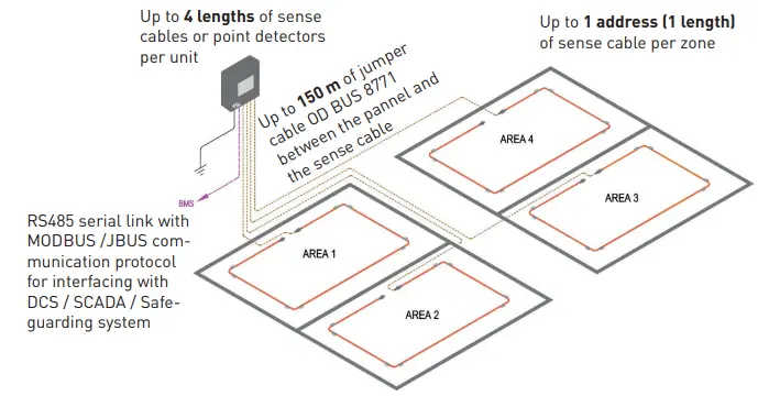
Layout Explanation (Figure 1.2.7):
- 4 detection zones are available.
- FG-ALS4-OD can control up to 1 address or 1 length (of 3, 7, 12 or 20m) of oil sense cable or point sensor per zone.
In total, up to 4 lengths (or 80m) of sense cables or point sensors per unit.
Different possibilities of configurations are:
- 1 cable per zone; or
- 2 cables in one zone et 0 cable in another ; or
- all of the 4 cables in one zone.
Point detector can be connected in the place of sense cables, see 1.3.2.
For a system with FG-ALS4 or FG-ALS4-OD unit:
- Between 2 lengths of sense cables: up to 150m of jumper cables.
- Total length of jumper cables on a unit: up to 300m.
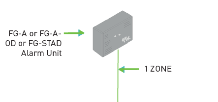
Alarm Unit: FG-A
The FG-A alarm unit is a non-locating unit. It is designed to be used with analog sense cables as FG-ECS, FG-ECX, FG-ACS and FG-ACX for water and acids leak detection.
Responses on the FG-A alarm unit:
- In the case of a leak, an audible alarm is triggered. The red LED on the front panel is switched on and the leak relay is activated.
- In the case of cable break, an audible alarm is triggered, the yellow LED on the front panel is switched on and the cable break relay is
activated.
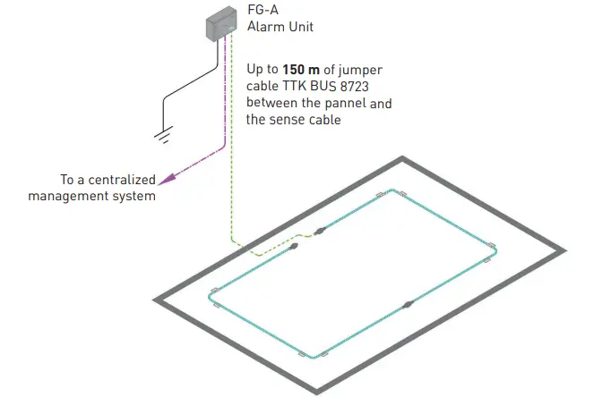
Layout Explanation (Figure 1.2.8):
- The FG-A unit has 1 circuit.
- It can control up to 15 metres of sense cables (either one length of FG-ECS / FG-ACS or several lengths of FG-ECX / FG-ACX).
Alarm Unit: FG-A-OD
The FG-A-OD alarm unit is a single sensor alarm unit. It is designed to be used exclusively with FG-OD hydrocarbon range of detectors for oil leak detection.
Responses on the FG-A-OD alarm unit:
- In the case of a leak, an audible alarm is triggered. The red LED on the front panel is switched on and the leak relay is activated.
- In the case of cable break, an audible alarm is triggered, the yellow LED on the front panel is switched on and the cable break relay is
activated.
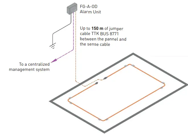
Figure 1.2.9 Layout with FG-A-OD
Layout Explanation (Figure 1.2.8):
- The FG-A-OD unit has 1 circuit.
- It can control one length of oil detection sense cable up to 20 metres.
Alarm Unit: FG-STAD
The standalone alarm unit FG-STAD is designed to be used with the TTK FG-OD range of hydrocarbon leak detection sense cables, or the hydro-carbon point sensor, FG-ODP. It monitors – in a fully stand-alone mode – one hydrocarbon leak point sensor or one sense cable. No voltage supply is needed, the panel is supplied with an embedded battery. There is no display on the FG-STAD panel. It is the interface between detectors and third-party supervision equipment thanks to its two single-pole outputs. One output reacts when the connected sense cable or point sensor is detected an oil leak, the other when a system fault appears.
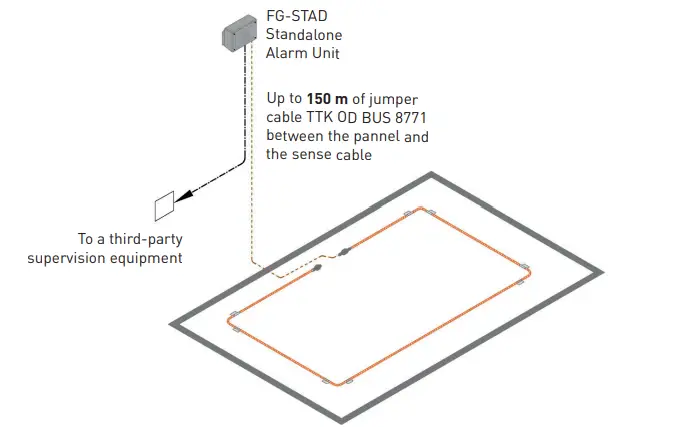
Figure 1.2.10 Layout with FG-STAD
Layout Explanation (Figure 1.2.10):
- The FG-STAD unit has 1 circuit.
- Up to 20 metres of sense cables (one length of FG-OD or a FG-ODP point sensor) can be connected on the FG-STAD.
Modbus Interface: FG-DTM
FG-DTM is a Modbus interface, designed to merge the product line of digital and analogue systems. It collects information from analogue panels and integrates them into the digital system. Therefore, the digital panel acts as central monitoring unit on which analogue panels and all connected sense cables circuits can be supervised. Meanwhile, each analogue panel acts as an independent local detection module.
Schematic 1
Basic integration of one analogue detection panel FG-ALS8 and analogue sense cables into a circuit of FG-NET digital panel.
DigitalPanel FG-NET Features:
- 8 configurable Relays
- 1 power Fail Relay
- 1 Ethernet Port (TCP/IP)
Modbus TCP/Emails/SNMP Traps Web Interface - 1 Serial Port
RS232/RS422/RS485 Modbus RTU
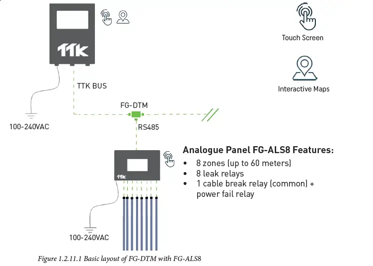
Layout Explanation (Figure 1.2.11.1):
- The FG-ALS8 can be replaced by a FG-ALS4.
Schematic 2
Integration of one analogue detection panels FG-ALS8 and analogue sense cables into a circuit of FG-BBOX panel, monitored by FG-NET panel via a standard Ethernet network.
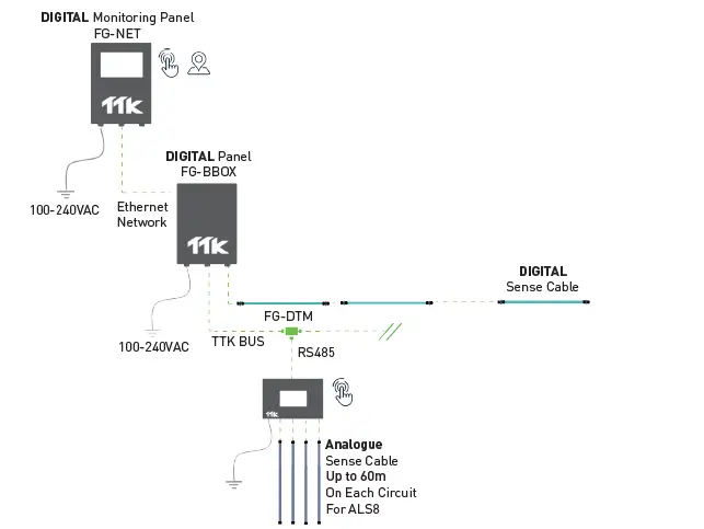
Figure 1.2.11.2 Layout of FG-DTM with FG-ALS8, FG-BBOX and FG-NET
Modbus Interface: FG-DTM (following)
Schematic 3
Integration of 4 analogue detection panels and analogue sense cables into a circuit of FG-NET digital panel, where other digital sense cables are connected.
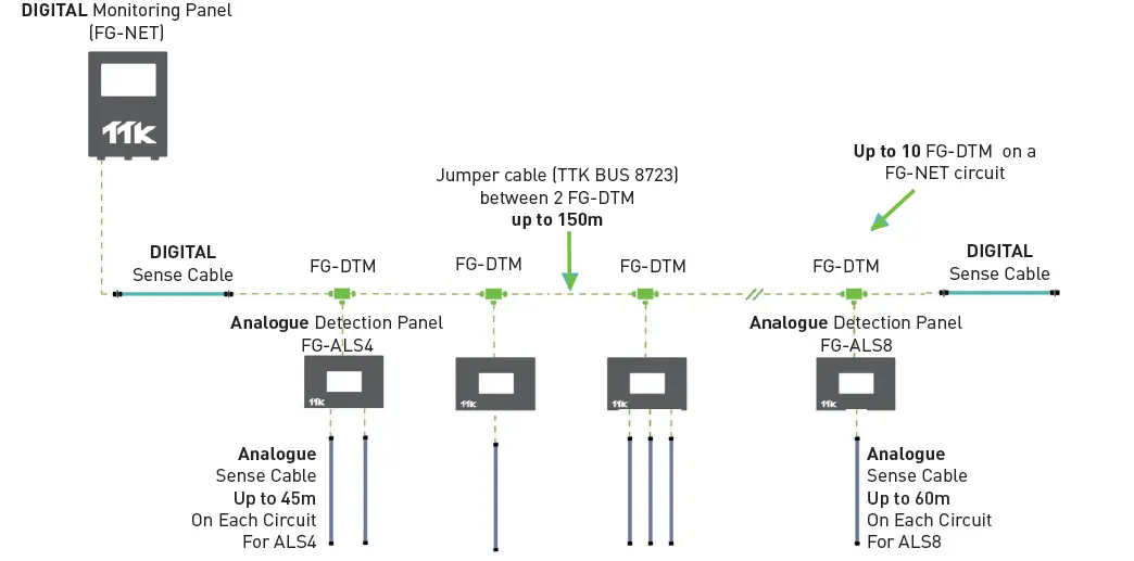
Figure 1.2.11.3 Layout of several FG-DTM with FG-NET
Layout Explanation (Figure 1.2.11.3):
- The FG-NET can be replaced by a FG-SYS or a FG-BBOX.
Schematic 4
Integration of 2 analogue detection panels into a circuit of FG-NET digital panel where a diversion box and analogue sense cables are connected.
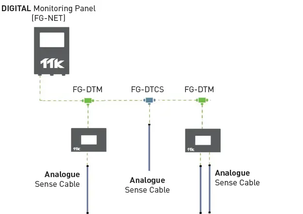
Figure 1.2.11 Layout of several FG-DTM with FG-ALS4/8 and FG-NET
Layout Explanation (Figure 1.2.11.3):
- The FG-NET can be replaced by a FG-SYS or a FG-BBOX.
- The analogue panel can be FG-ALS8 or FG-ALS4.
Point Sensors
In some situations, point sensors (probes) may better adapt the specific environment than sense cables.
Below are 2 Point Sensors, designed to be used with TTK digital units and alarm & locating system units for instant detection of liquid leaks.
Addressable Water Point Sensor: FG-ECP
- The FG-ECP, point sensor for water leak detection, is suitable to be used in environment such as lift pit and drip tray.
- The point sensor is available in two models: sense cable in ‘‘U’’ form and ‘‘L’’ form to suit different environments.
- It is designed to be used with FG-NET, FG-BBOX and FG-SYS digital units.
- Up to 40 x FG-ECP point sensors per digital unit circuit can be connected.
- FG-ECP point sensor can be mixed connected with FG-EC sense cables in one circuit on a digital unit (see figure 1.3.1.2).
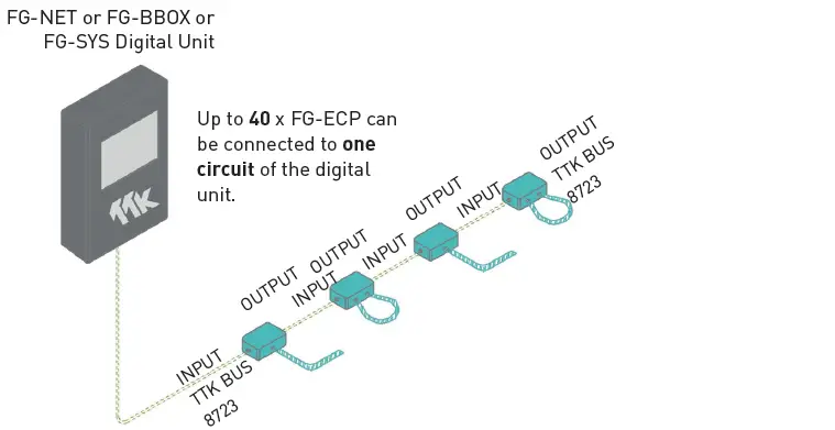
Figure 1.3.1: Layout of FG-ECP with FG-NET

Figure 1.3.1.2: Layout of mixed connection of point sensors FG-ECP and digital sense cables FG-EC on a circuit of FG-NET digital unit
Addressable Hydrocarbon Point Sensor: FG-ODP
- The FG-ODP, point sensor for liquid hydrocarbon and non-conductive solvent leak detection, is suitable to detect hydrocarbon floating on water, for example on tank and pit application.
- It should always be connected on a point sensor diversion box FG-DOP before connecting to a locating unit FG-NET-LL, FG-BBOX-LL, FG-ALS8-OD or FG-ALS4-OD having OD BUS 8771 output. The diversion box is not necessary when connecting to a FG-A-OD or FG-STAD.
- The point sensor is compatible with FG-NET-LL, FG-BBOX-LL, FG-ALS8-OD or FG-ALS4-OD Locating Unit (with OD BUS 8771 output). It is also compatible with FG-NET and FG-BBOX digital units (with BUS 8723 output) but need to install an extra interfacing box FG-DOD between (more details see 1.4.7 mixed layout with FG-DOD and FG-DOP).
- Up to 40 x FG-ODP point sensors per FG-NET-LL or FG-BBOX-LL digital unit circuit.
- Up to 8 x FG-ODP point sensors per FG-ALS8-OD locating unit.
- Up to 4 x FG-ODP point sensors per FG-ALS4-OD locating unit.
- 1 x FG-ODP point sensor per FG-A-OD non-locating unit.
- 1 x FG-ODP point sensor per FG-STAD ‘stand-alone’ unit.
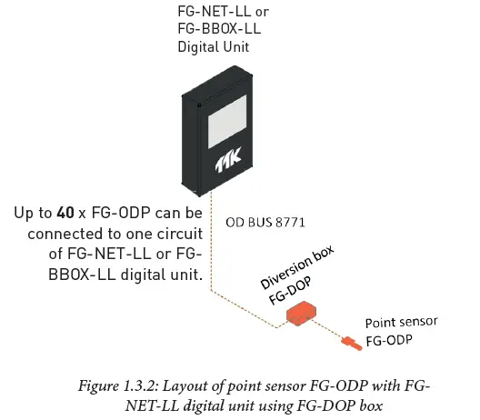
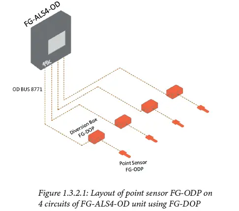
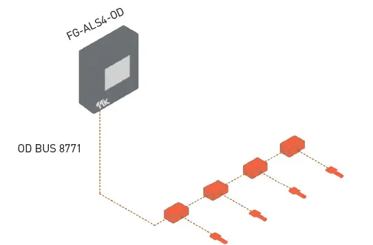
Figure 1.3.2.2: Layout of point sensor FG-ODP on 1 circuit of FG-ALS4-OD unit using FG-DOP
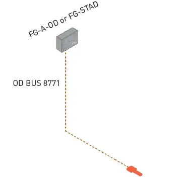 Figure 1.3.2.3: Layout of point sensor FG-ODP with FG-A-OD or FG-STAD alarm unit using FG-DOP box
Same design principle on a FG-ALS8-OD unit as on a FG-ALS4-OD unit.
Layout Explanation (Figure 1.3.2.1, 1.3.2.2):
- Up to 4 x FG-ODP can be connected to one FG-ALS4-OD locating unit.
- 2 possibilities to connect up to 4 FG-DOP + FG-ODP on FG-ALS4-OD unit:
- either 4 point sensors on 4 different zones (as figure 1.3.2.1);
- or on the same zone (as figure 1.3.2.2).
Boxes
In order to fit the complex installation, TTK offers different kinds of boxes: such as FG-DTC, FG-DTCS, FG-DCTL and FG-DOD. They have their own characteristics but all of them facilitate the extension of the system in different situation.
Layouts in session 1.4 explain different situation.
Diversion Box: FG-DTC
- The digital diversion box FG-DTC makes it possible to split a detection circuit into two parts, so as to allow the system to cover more horizontal space (figure 1.4.1).

Addressable Box: FG-DTCS
- The addressable sector box FG-DTCS allows connecting digital unit FG-NET with analog sense cables and makes these cables addressable, in the meantime it has a unique advantage to cover vertical space (as illustrated in figure 1.4.2).
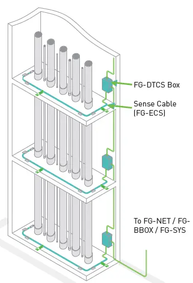
Figure 1.4.2: Layout with addressable box FG-DTCS

Figure 1.4.2.1: Addressable box FG-DTCS cabling diagram
FG-ECS Sense Cable:
- FG-ECS cable is an analog water sense cable (without micro-chip).
- Each cable includes a jumper cable and an end termination at two tips.
- The standard lengths are 3, 7 and 15m.
Design Tips:
- FG-DTCS box is designed to use with FG-ECS and FG-ACS analog sense cables (above two figures use FG-ECS cable as example).
- FG-DTCS box has advantages when used for similar small to midium size space on different levels (vertical areas) as sector layout.
Mixed Layout With FG-DTC & FG-DTCS Boxes
- In real installation, FG-NET system layout could be complex. A mixed installation of FG-DTC and FG-DTCS boxes could ease installation, it allows extension of the system.
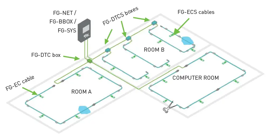
Figure 1.4.3 : Layout with FG-DTC et FG-DTCS boxes
Design Tips:
- Use jumper cable for wall or corridor passage between two sense cables. Maximum jumper cable length for each FG-NET output is 150 metre.
- FG-EC cables can be daisy-chained, this is used for horizontal extension (on wide areas on the same floor).
- FG-ECS cables (without connector) has a termination at end tip of the cable, it is recommanded to use for vertical extension (on different floors).
Layout Explanation (Figure 1.4.3) :
- The system uses one FG-DTC box and three FG-DTCS boxes.
- Both ROOM A and COMPUTER ROOM are protected by four FG-EC sense cables. These cables are connected to the first circuit of the panel via a FG-DTC box.
- ROOM B is protected by three sector sense cables FG-ECS via 3 FG-DTCS boxes.
- In this installation, the panel will trigger 3 alarms:
- leak alarm in ROOM A with +/-1m leak precision;
- leak alarm in ROOM B indicating the alarming cable;
- cablebreak alarm in COMPUTER ROOM +/-1m leak precision (all upstream cables in COMPUTER ROOM still functioning).
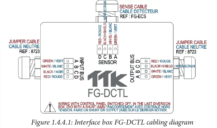
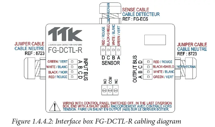
‘Cut-To-Length’ Addressable Box: FG-DCTL / FG-DCTL-R
- The FG-DCTL addressable box allows the connection of one analog sense cable (1 to 45m, ‘‘Cut-To-Length’’) to the main BUS wire from the digital panel.
- FG-DCTL will create an address on the panel for that sense cable.
- The LED on the front face of the box indicates the box’s status in real time.
- 2 references are available: FG-DCTL and FG-DCTL-R. The only difference: FG-DCTL-R is equipped with a relay (230Vac-1A), activated in case of leak; not for FG-DCTL.
- Maximum 30 FG-DCTL Box per circuit.
Layout Explanation (Figure 1.4.4):
- FG-DCTL is compatible with FG-NET, FG-BBOX and FG-SYS digital units.
- FG-DCTL is compatible with sense cables as FG-ECS and FG-ACS random (length from 1 to 45m).
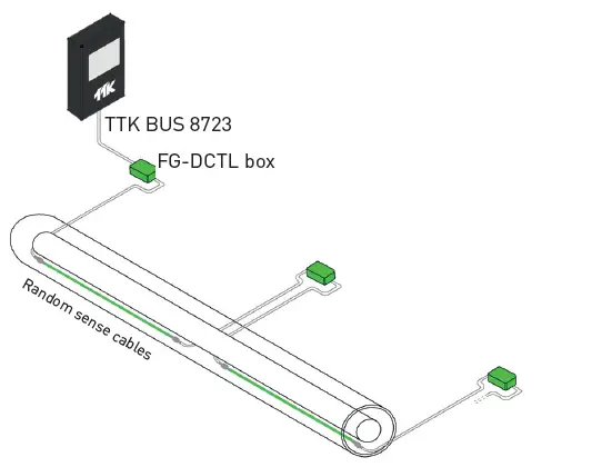
Figure 1.4.4 : Layout with FG-DCTL interface box
Interface Box: FG-DOD
- FG-DOD is an OD BUS interface box.
- It is used for FG-OD sense cables installed in combination with a water / acids installation on FG-NET / FG-BBOX digital units.
- It will split a standard BUS into two outputs, the first one being ATEX approved and dedicated to FG-OD sense cables, and the second one being dedicated to water / acids sense cables or to another box (see figure 1.4.5.1).
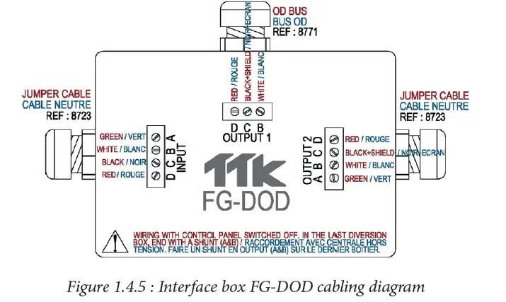
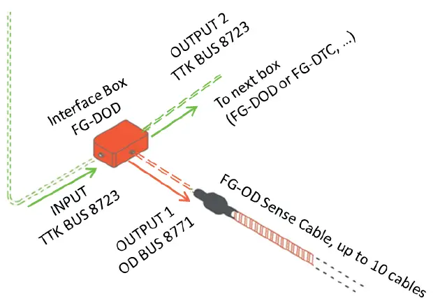
Figure 1.4.5.1: Connection of interface box FG-DOD
Layout Explanation (Figure 1.4.5.1):
- Up to 10 x FG-OD sense cables (on OUTPUT 1) can be connected to one interface box FG-DOD.
- On OUTPUT 2, diversion box or interface box can be connected.
- FG-DOD works as an interface between FG-NET digital unit (with TTK BUS 8723 output) and FG-OD sense cables (with OD BUS 8771 output).
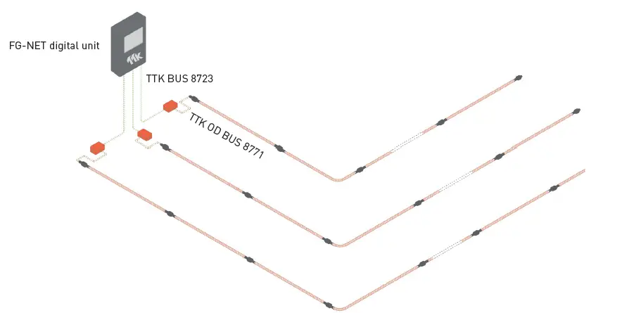
Figure 1.4.5.2: Layout of digital unit FG-NET and sense cable FG-OD using interface boxes FG-DOD
Point Sensor Diversion Box: FG-DOP
- FG-DOP is a point sensor diversion box. It is a connection box for integration of the point sensor FG-ODP on an OD BUS 8771. For example, in figure 1.4.6.1 below, the FG-DOP boxes allow the series connection of the point sensors FG-ODP.
- The box is mandatory when connecting on FG-NET-LL, FG-BBOX-LL or FG-ALS4 / 8-OD.
- The box is not required when connecting on FG-A-OD or FG-STAD.
- More layout examples with FG-ALS4-OD see 1.3.2.
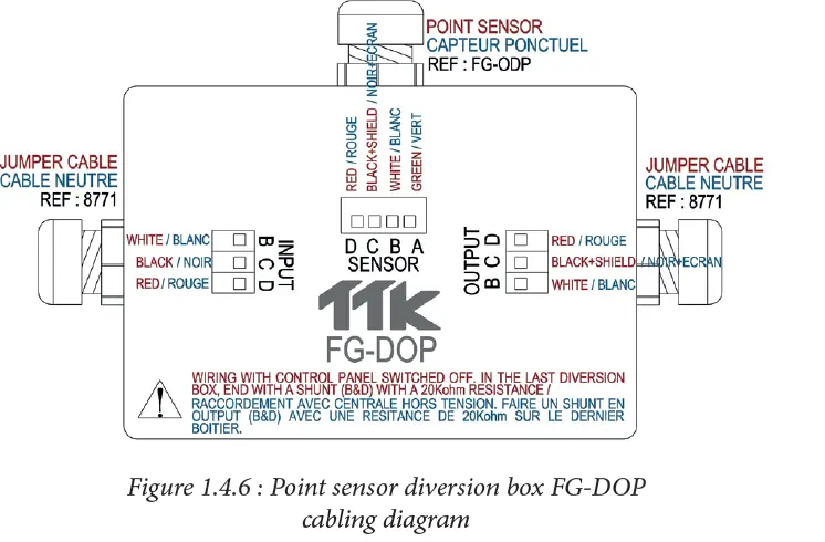
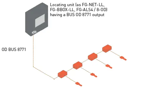
Figure 1.4.6.1: Layout of point sensor FG-ODP on digital locating unit using FG-DOP
Mixed Layout With FG-DOD & FG-DOP Boxes
- A mixed use of boxes FG-DOD and FG-DOP allows the connection of digital units with TTK BUS 8723 (FG-NET, FG-BBOX) outputs to point sensor FG-ODP.
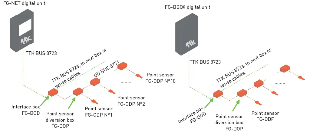
Figure 1.4.7 : Layout of mixed use of FG-DOD and FG-DOP boxes on FG-NET and FG-BBOX units
Layout Explanation (Figure 1.4.7):
- Up to 40 x FG-ODP can be connected to one circuit of FG-NET / FG-BBOX digital unit.
- Up to 10 x diversion box FG-DOP + point sensor FG-ODP can be connected on 1 interface box FG-DOD
Horizontal Layout On Three Outputs
FG-SYS / FG-NET Digital Unit has 3 outputs. They can be used for both horizontal and vertical installation for a larger extension. The layout
presented below (figure 1.5) is a horizontal layout.
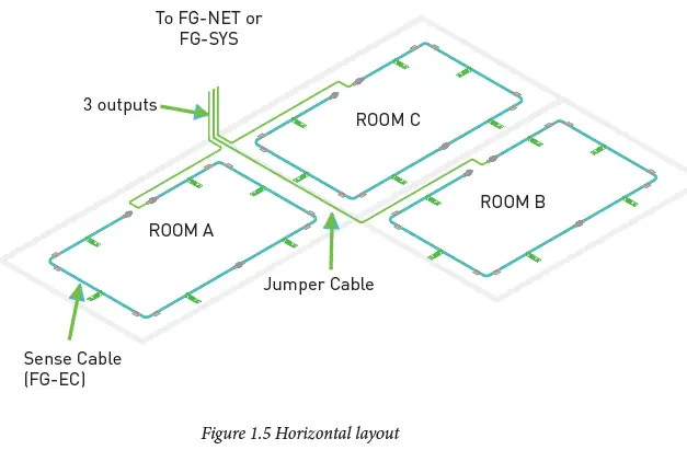
Layout Explanation (Figure 1.5) :
- The system uses all the three outputs of a FG-SYS / FG-NET unit.
- Each output starts from FG-SYS / FG-NET with jumper cable for wall passage till the zone of protection.
- Output 1 goes to room A;
- Output 2 goes to room B;
- Output 3 goes to room C.
- Each output is independent. Room A, B and C are totally independent.
Installation Tips (Figure 1.5) :
- Hold-down clips with adhesive are recommended every 1.5 metres or where required.
- An end termination is indispensable for the last sensing cable of one circuit.
Vertical Layout On Three Outputs
For a vertical installation in building environment, FG-SYS / FG-NET three outputs are designed for providing extensions to several floors.
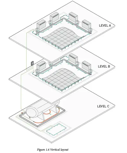
Layout Explanation (Figure 1.6) :
- A single digital panel is enough to manage sense cables installed on these three levels.
- Each output starts from FG-SYS / FG-NET with jumper cable for wall passage till the zone of protection.
- On level C, FG-DOD is used for the connection with FG-OD sense cable.
- Each output is independent. Thus floor A, B and C are totally independently under control, to ensure a best security.
Three Typical Digital Sense Cable Layouts
In order to fit different installation situation and client’s requirements, TTK suggests three typical layouts to protect an area.
Extensive Density Protection
Typical ‘very important place’ extensive density protection, allowing peri-metre and total floor coverage of the room.
Typical application:
Mission critical facilities, data center, hospital, emergency call center, airport control centre, expensive equipments/machines, UPS room, etc.
Typical and the most commun design for prevent external liquid leak come inside the protected zone. Sensing cable typically installed about 1 metre from the walls.
Typical application:
Offices, archives room, kitchen, toilets, technical room, tank room, lift pit, etc.
Figures 1.7 Three typical layouts
Typical design for air-conditionners and leak possible objects, prevent leaks extend without acknowledge. Sensing cable typically installed about 75cm in front of and near the air-outlet of machines.
Typical application:
ACU room, comms room, vending areas, etc.
External Relays Box: FG-RELAYS
The FG-RELAYS is a digital external relays box. It works as a satellite device of the FG-NET digital unit. It adds a set of 24 configurable external relays to the FG-NET. It allows FG-NET to drive external devices such as solenoid valves, BMS signals, beacons and others, to react in case of leak or system alarms.
Layout Explanation (Figure 1.8) :
- FG-RELAYS N°1, N°2,… N°16 are connected to FG-NET via Ethernet. They are presented as FG-RELAYS #1, FG-RELAYS #2 and so on displayed on the FG-NET Digital Unit.
- FG-RELAYS box status can be viewed on the FG-NET digital unit. In case of box disconnected, FG-NET displays an alarm and the general relay is activated.
- The FG-RELAYS is accessible via a web interface for configuration.
- Up to 16 FG-RELAYS boxes can be managed by one FG-NET allowing for a maximum of 384 (24×16) additional relays.
PART 2 APPLICATIONS
Data Center, Air-Conditioner Room Applications
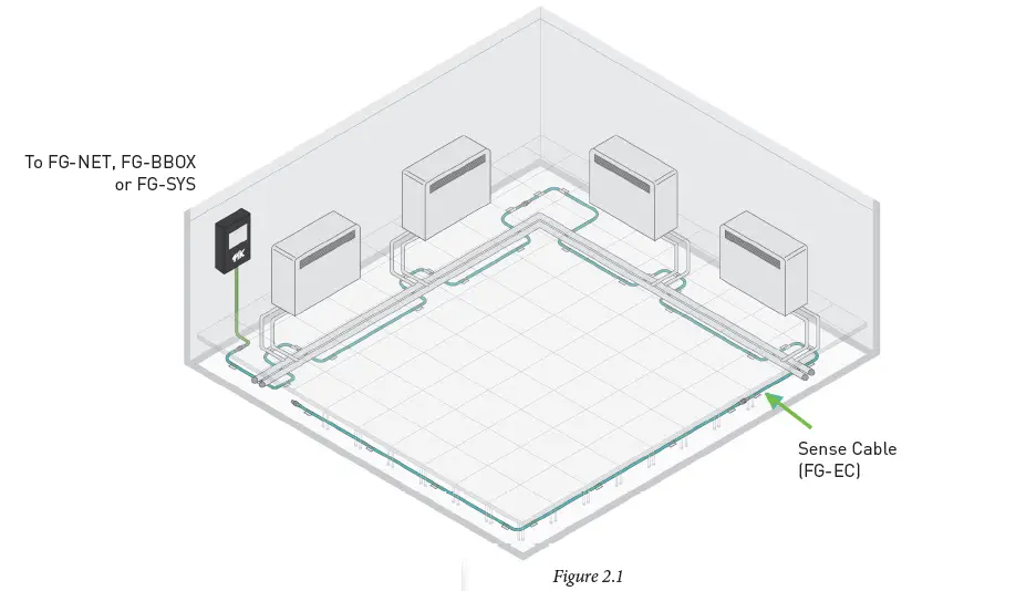
Layout Explanation (Figure 2.1) :
- Four Air Conditoner Uints (ACUs) are installed in the perimetre of the room.
- In this case, sense cables (FG-EC) are installed in the perimetre of the room and in front of the (ACUs).
- This installation is to prevent leaks from ACUs and prevent external leaks from entering the room.
Note:
- Suggest to place Sensing Cables 75cm in front of the air outlet of air-conditionning unit.
Design Tip:
- FG-OD is NOT compatible with FG-SYS digital unit.
- To connect to FG-NET or FG-BBOX, an interface box FG-DOD is enquired.
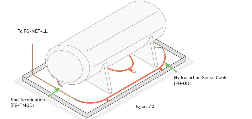
Layout Explanation (Figure 2.2) :
- This figure is a typical installation for fuel tank and generator.
- FG-OD sense cables are installed in the perimetre of the equipment.
- This installation is to prevent leaks from the technical equipment.
- For more information about the application examples of FG-OD, refer to hydrocarbon system Design Guides.
FG-OD Digital Oil Sense Cable:
- FG-OD detects the presence of liquids hydrocarbon and solvents.
- Fast response and re-usable after leak detection.
- Suitable for dangerous zones of explosive atmosphere
- Zener Barrier: Ex ia IIB T4 Ga (ATEX “Zone 0”).
Indoor Water Pipe Application
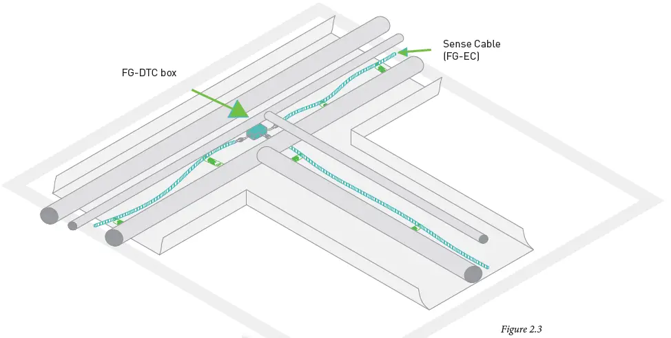
Layout Explanation (Figure 2.3) :
- Sense cables (FG-EC) are installed in the drip trays under pipes.
- This installation makes sure an immediate detection for any leak from the pipe.
- Diversion box allows the circuit extends to two parts so as to cover more pipes.
For pipe with insulation (without drip tray), figure 2.3.1 et figure 2.3.2 present two kinds of water sensing cable installation.

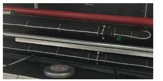
Photo 2.3.1
Layout Explanation (photo 2.3.1) :
- Sense cables FG-ECB is equipped with an external polyethylene based braided jacket and is specially designed for pipes solution.
- FG-ECB is to be installed under the suspended pipes, to be belt on the bottom of these pipes. The drip tray is not compulsory.
Layout Explanation (Figure 2.3.1 & Figure 2.3.2) :
- The sense cable FG-ECB is installed outside the insulation, on the outside diameter of the mechanical protection sleeve.(Figure 2.3.1);
- The sense cable is installed inside the insulation, on the outside diameter of and under the chilled water pipe (In this case, take into account of condensation phenomena) (Figure 2.3.2).
- Both installations assure an immediate detection for any leak from the pipe, the typical application when the pipes are not equipped with the drip tray.
Application for Several Levels in One Building
FG-SYS / FG-NET locating systems are flexible, from a small area to several big areas, they fit the situation. Both systems have unique advantages in multiple level buildings.
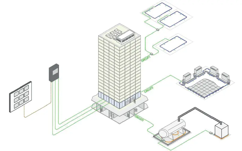
Layout explanations (Figure 2.4) :
- The digital unit uses 3 outputs to go to different levels, thus to cover all places that need protection in the whole building.
- Each output has capacity till 600m cables, thus in total 1800m cables can be connected to only 1 digital unit. FG-NET can connect with satellite devices FG-BBOX (up to 1200m of sense cables per device, ref to chapiter 1.7)
- Three possibilities to exploit the information on the digital unit:
- RJ45 port for connecting network-Protocol TCP / IP;
- RS232 or RS422/485series links – JBUS / ModBUS protocol;
- 9 relays: 8 fully configurable relays and one specific relay for power failure.
- The alarm panel is installed in ground floor security office for supervising the whole building.
Documents / Resources
 |
TTK FG-NET Leak Detection and Locating Systems [pdf] User Guide FG-NET, FG-BBOX, FG-ALS8, FG-ALS8-OD, FG-ALS4, FG-NET Leak Detection and Locating Systems, FG-NET, Leak Detection and Locating Systems, Detection and Locating Systems, and Locating Systems, Locating Systems, Systems |


