ESPC6WROOM1 N16 Module Espressif System
Specifications
- Module Name: ESP32-C6-WROOM-1
- Wireless Connectivity: Wi-Fi, IEEE 802.15.4, Bluetooth LE
- Processor: ESP32-C6, 32-bit RISC-V single-core
- Flash Options: 4MB, 8MB, 16MB (Quad SPI)
Product Usage Instructions
Get Started
What You Need
To get started with the ESP32-C6-WROOM-1 module, you will need:
- ESP32-C6-WROOM-1 module
- Hardware components for connection
- Development environment setup
Hardware Connection
Refer to the pin layout diagram for connecting the necessary hardware components to the module.
Set up Development Environment
- Install Prerequisites: Install the necessary software tools as per the requirements.
- Get ESP-IDF: Obtain the ESP-IDF (Espressif IoT Development Framework) for development.
- Set up Tools: Configure the development tools required for programming.
- Set up Environment Variables: Set up environment variables for the development environment.
Create Your First Project
Follow these steps to create your first project with the ESP32-C6-WROOM-1 module:
- Start a Project: Begin a new project in your development environment.
- Connect Your Device: Connect the ESP32-C6-WROOM-1 module to your development setup.
- Configure: Configure the project settings and peripherals as needed.
- Build the Project: Build the project to generate the firmware.
- Flash onto the Device: Flash the firmware onto the ESP32-C6-WROOM-1 module.
- Monitor: Monitor the output and behavior of your project.
Module that supports 2.4 GHz Wi-Fi 6 (802.11 ax), Bluetooth® 5 (LE), Zigbee and Thread
(802.15.4)
Built around ESP32-C6 series of SoCs, 32-bit RISC-V single-core microprocessor
Flash up to 16 MB
23 GPIOs, rich set of peripherals
On-board PCB antenna
Module Overview
Features
- CPU and On-Chip Memory
- ESP32-C6 embedded, 32-bit RISC-V single-core microprocessor, up to 160 MHz
- ROM: 320 KB
- HP SRAM: 512 KB
- LP SRAM: 16 KB
- Wi-Fi
- 1T1R in 2.4 GHz band
- Operating frequency: 2412 ~ 2462 MHz
- IEEE 802.11ax-compliant
- 20 MHz-only non-AP mode
- MCS0 ~MCS9
- Uplink and downlink OFDMA, especially suitable for simultaneous connections in high-density environments
- Downlink MU-MIMO (multi-user, multiple input, multiple output) to increase network capacity
- Beamformee that improves signal quality
- Channel quality indication (CQI)
- DCM (dual carrier modulation) to improve link robustness
- Spatial reuse to maximize parallel transmissions
- Target wake time (TWT) that optimizes power saving mechanisms
- Fully compatible with IEEE 802.11b/g/n protocol
- 20 MHz and 40 MHz bandwidth
- Data rate up to 150 Mbps
- Wi-Fi Multimedia (WMM)
- TX/RX A-MPDU, TX/RX A-MSDU
- Immediate Block ACK
- Fragmentation and defragmentation
- Transmit opportunity (TXOP)
- Automatic Beacon monitoring (hardware TSF)
- 4 × virtual Wi-Fi interfaces
- Simultaneous support for Infrastructure BSS in Station mode, SoftAP mode, Station + SoftAP mode, and promiscuous mode
Note that when ESP32-C6 scans in Station mode, the SoftAP channel will change along with the Station channel - 802.11mc FTM
- Bluetooth®
- Bluetooth LE: Bluetooth 5.3 certified
- Bluetooth mesh
- High power mode
- Speed: 1 Mbps, 2 Mbps
- Advertising extensions
- Multiple advertisement sets
- Channel selection algorithm #2
- LE power control
- Internal co-existence mechanism between Wi-Fi and Bluetooth to share the same antenna
- IEEE 802.15.4
- Compliant with IEEE 802.15.4-2015 protocol
- OQPSK PHY in 2.4 GHz band
- Data rate: 250 Kbps
- Thread 1.3
- Zigbee 3.0
- Peripherals
- GPIO, SPI, parallel IO interface, UART, I2C, I2S,RMT (TX/RX), pulse counter, LED PWM, USB Serial/JTAG controller, MCPWM, SDIO2.0 slave controller, GDMA, TWAI® controller, on-chip debug functionality via JTAG, event task matrix,ADC, temperature sensor, general-purpose timers, watchdog timers, etc.
Integrated Components on Module - 40 MHz crystal oscillator
- SPI flash
- GPIO, SPI, parallel IO interface, UART, I2C, I2S,RMT (TX/RX), pulse counter, LED PWM, USB Serial/JTAG controller, MCPWM, SDIO2.0 slave controller, GDMA, TWAI® controller, on-chip debug functionality via JTAG, event task matrix,ADC, temperature sensor, general-purpose timers, watchdog timers, etc.
- Antenna Options
- On-board PCB antenna
- Operating Conditions
- Operating voltage/Power supply: 3.0 ~ 3.6 V
- Operating ambient temperature:
- 85 °C version module: –40 ~ 85 °C
- 105 °C version module: –40 ~ 105 °C
Description
ESP32-C6-WROOM-1 is a general-purpose Wi-Fi, IEEE 802.15.4, and Bluetooth LE module. The rich set of peripherals and high performance make the module an ideal choice for smart homes, industrial automation, health care, consumer electronics, etc.
ESP32-C6-WROOM-1 module features an external SPI flash.
The ordering information for ESP32-C6-WROOM-1 is as follows:
Table 1: ESP32-C6-WROOM-1 Ordering Information
| Ordering Code | Flash | Ambient Temp.
(°C) |
Size
(mm) |
| ESP32-C6-WROOM-1-N4 | 4 MB (Quad SPI) | –40 ∼ 85 |
18.0 × 25.5 × 3.1 |
| ESP32-C6-WROOM-1-H4 | –40 ∼ 105 | ||
| ESP32-C6-WROOM-1-N8 | 8 MB (Quad SPI) | –40 ∼ 85 | |
| ESP32-C6-WROOM-1-N16 | 16 MB (Quad SPI) |
At the core of this module is ESP32-C6, a 32-bit RISC-V single-core processor.
ESP32-C6 integrates a rich set of peripherals including SPI, parallel IO interface, UART, I2C, I2S, RMT (TX/RX),LED PWM, USB Serial/JTAG controller, MCPWM, SDIO2.0 slave controller, GDMA, TWAI® controller, on-chip debug functionality via JTAG, event task matrix, as well as up to 23 GPIOs, etc.
Note:
For more information on ESP32-C6, please refer to ESP32-C6 Series Datasheet.
Pin Definitions
Pin Layout
The pin diagram below shows the approximate location of pins on the module.
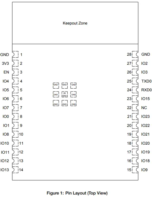
Pin Description
The module has 29 pins. See pin definitions in Table 2 Pin Definitions.
For peripheral pin configurations, please refer to ESP32-C6 Series Datasheet.
Table 2: Pin Definitions
| Name | No. | Type1 | Function |
| GND | 1 | P | Ground |
| 3V3 | 2 | P | Power supply |
| EN | 3 | I | High: on, enables the chip. Low: off, the chip powers off.
Note: Do not leave the EN pin floating. |
| IO4 | 4 | I/O/T | MTMS, GPIO4, LP_GPIO4, LP_UART_RXD, ADC1_CH4, FSPIHD |
| IO5 | 5 | I/O/T | MTDI, GPIO5, LP_GPIO5, LP_UART_TXD, ADC1_CH5, FSPIWP |
| IO6 | 6 | I/O/T | MTCK, GPIO6, LP_GPIO6, LP_I2C_SDA, ADC1_CH6, FSPICLK |
| IO7 | 7 | I/O/T | MTDO, GPIO7, LP_GPIO7, LP_I2C_SCL, FSPID |
| IO0 | 8 | I/O/T | GPIO0, XTAL_32K_P, LP_GPIO0, LP_UART_DTRN, ADC1_CH0 |
| IO1 | 9 | I/O/T | GPIO1, XTAL_32K_N, LP_GPIO1, LP_UART_DSRN, ADC1_CH1 |
| IO8 | 10 | I/O/T | GPIO8 |
| IO10 | 11 | I/O/T | GPIO10 |
| IO11 | 12 | I/O/T | GPIO11 |
| IO12 | 13 | I/O/T | GPIO12, USB_D- |
| IO13 | 14 | I/O/T | GPIO13, USB_D+ |
| IO9 | 15 | I/O/T | GPIO9 |
| IO18 | 16 | I/O/T | GPIO18, SDIO_CMD, FSPICS2 |
| IO19 | 17 | I/O/T | GPIO19, SDIO_CLK, FSPICS3 |
| IO20 | 18 | I/O/T | GPIO20, SDIO_DATA0, FSPICS4 |
| IO21 | 19 | I/O/T | GPIO21, SDIO_DATA1, FSPICS5 |
| IO22 | 20 | I/O/T | GPIO22, SDIO_DATA2 |
| IO23 | 21 | I/O/T | GPIO23, SDIO_DATA3 |
| NC | 22 | — | NC |
| IO15 | 23 | I/O/T | GPIO15 |
| RXD0 | 24 | I/O/T | U0RXD, GPIO17, FSPICS1 |
| TXD0 | 25 | I/O/T | U0TXD, GPIO16, FSPICS0 |
| IO3 | 26 | I/O/T | GPIO3, LP_GPIO3, LP_UART_CTSN, ADC1_CH3 |
| IO2 | 27 | I/O/T | GPIO2, LP_GPIO2, LP_UART_RTSN, ADC1_CH2, FSPIQ |
| GND | 28 | P | Ground |
| EPAD | 29 | P | Ground |
1 P: power supply; I: input; O: output; T: high impedance.
Get Started
What You Need
To develop applications for module you need:
- 1 x ESP32-C6-WROOM-1
- 1 x Espressif RF testing board
- 1 x USB-to-Serial board
- 1 x Micro-USB cable
- 1 x PC running Linux
In this user guide, we take Linux operating system as an example. For more information about the configuration on Windows and macOS, please refer to ESP-IDF Programming Guide.
Hardware Connection
- Solder the ESP32-C6-WROOM-1 module to the RF testing board as shown in Figure 2.

- Connect the RF testing board to the USB-to-Serial board via TXD, RXD, and GND.
- Connect the USB-to-Serial board to the PC.
- Connect the RF testing board to the PC or a power adapter to enable 5 V power supply, via the Micro-USB cable.
- During download, connect IO9 to GND via a jumper. Then, turn ”ON” the testing board.
- Download firmware into flash. For details, see the sections below.
- After download, remove the jumper on IO9 and GND.
- Power up the RF testing board again. The module will switch to working mode. The chip will read programs from flash upon initialization.
Note:
IO9 is internally logic high. If IO9 is set to pull-up, the Boot mode is selected. If this pin is pull-down or left floating, the
Download mode is selected. For more information on ESP32-C6-WROOM-1, please refer to ESP32-C6 Series Datasheet.
Set up Development Environment
The Espressif IoT Development Framework (ESP-IDF for short) is a framework for developing applications based on the Espressif ESP32. Users can develop applications with ESP32-C6 in Windows/Linux/macOS based on ESP-IDF. Here we take Linux operating system as an example.
- Install Prerequisites
To compile with ESP-IDF you need to get the following packages:- CentOS 7 & 8:

- Ubuntu and Debian:

- Arch:

Note:- This guide uses the directory ~/esp on Linux as an installation folder for ESP-IDF.
- Keep in mind that ESP-IDF does not support spaces in paths.
- CentOS 7 & 8:
- Get ESP-IDF
To build applications for ESP32-C6-WROOM-1 module, you need the software libraries provided by Espressif in ESP-IDF repository.
To get ESP-IDF, create an installation directory (~/esp) to download ESP-IDF to and clone the repository with ‘git clone’:
ESP-IDF will be downloaded into ~/esp/esp-idf. Consult ESP-IDF Versions for information about which ESP-IDF version to use in a given situation. - Set up Tools
Aside from the ESP-IDF, you also need to install the tools used by ESP-IDF, such as the compiler, debugger,Python packages, etc. ESP-IDF provides a script named ’install.sh’ to help set up the tools in one go.
- Set up Environment Variables
The installed tools are not yet added to the PATH environment variable. To make the tools usable from the command line, some environment variables must be set. ESP-IDF provides another script ’export.sh’ which does that. In the terminal where you are going to use ESP-IDF, run:
Now everything is ready, you can build your first project on ESP32-C6-WROOM-1 module.
Create Your First Project
- Start a Project
Now you are ready to prepare your application for ESP32-C6-WROOM-1 module. You can start with get-started/hello_world project from examples directory in ESP-IDF.
Copy get-started/hello_world to ~/esp directory: There is a range of example projects in the examples directory in ESP-IDF. You can copy any project in the same way as presented above and run it. It is also possible to build examples in-place, without copying them first.
 - Connect Your Device
Now connect your module to the computer and check under what serial port the module is visible. Serial ports in Linux start with ‘/dev/tty’ in their names. Run the command below two times, first with the board unplugged, then with plugged in. The port which appears the second time is the one you need: Note:Keep the port name handy as you will need it in the next steps.
 - Configure
Navigate to your ‘hello_world’ directory from Step 3.4.1. Start a Project, set ESP32-C6 chip as the target and run the project configuration utility ‘menuconfig’.
Setting the target with ‘idf.py set-target ESP32-C6’ should be done once, after opening a new project. If the project contains some existing builds and configuration, they will be cleared and initialized. The target may be saved in environment variable to skip this step at all. See Selecting the Target for additional information.
If the previous steps have been done correctly, the following menu appears:
You are using this menu to set up project specific variables, e.g. Wi-Fi network name and password, the
processor speed, etc. Setting up the project with menuconfig may be skipped for “hello_word”. This example will
run with default configuration
The colors of the menu could be different in your terminal. You can change the appearance with the option ‘–style’. Please run ‘idf.py menuconfig –help’–for further information. - Build the Project
Build the project by running:
This command will compile the application and all ESP-IDF components, then it will generate the bootloader,partition table, and application binaries.

If there are no errors, the build will finish by generating the firmware binary .bin file. - Flash onto the Device
Flash the binaries that you just built onto your module by running:
Replace PORT with your ESP32-C6 board’s serial port name from Step: Connect Your Device.
You can also change the flasher baud rate by replacing BAUD with the baud rate you need. The default baud rate is 460800.
For more information on idf.py arguments, see idf.py.
Note:
The option ‘flash‘ automatically builds and flashes the project, so running ‘idf.py build‘ is not necessary.
When flashing, you will see the output log similar to the following:


If there are no issues by the end of the flash process, the board will reboot and start up the “hello_world” application. - Monitor
To check if “hello_world” is indeed running, type ‘idf.py -p PORT monitor‘ (Do not forget to replace PORT with your serial port name).
This command launches the IDF Monitor application:
 After startup and diagnostic logs scroll up, you should see “Hello world!” printed out by the application.
To exit IDF monitor use the shortcut Ctrl+].
That’s all what you need to get started with ESP32-C6-WROOM-1 module! Now you are ready to try some other examples in ESP-IDF, or go right to developing your own applications.
U.S. FCC Statement
The device complies with KDB 996369 D03 OEM Manual v01. Below are integration instructions for host product manufacturers according to the KDB 996369 D03 OEM Manual v01.
List of Applicable FCC Rules
FCC Part 15 Subpart C 15.247
Specific Operational Use Conditions
The module has WiFi and BLE functions.
- Operation Frequency:
- WiFi: 2412 ~ 2462 MHz
- Bluetooth: 2402 ~ 2480 MHz
- Zigbee/Thread:2405 ~ 2480 MHz
- Number of Channel:
- WiFi: 11
- Bluetooth: 40
- Zigbee/Thread: 26
- Modulation:
- WiFi: DSSS; OFDM
- Bluetooth: GFSK
- Zigbee/Thread:O-QPSK
- Type: On-board PCB Antenna
- Gain: 3.26 dBi Max
The module can be used for IoT applications with a maximum 3.26 dBi antenna. The host manufacturer installing this module into their product must ensure that the final composit product complies with the FCC requirements by a technical assessment or evaluation to the FCC rules, including the transmitter operation. The host manufacturer has to be aware not to provide information to the end user regarding how to install or remove this RF module in the user’s manual of the end product which integrates this module. The end user manual shall include all required regulatory information/warning as show in this manual.
Limited Module Procedures
Not applicable. The module is a single module and complies with the requirement of FCC Part 15.212.
Trace Antenna Designs
Not applicable. The module has its own antenna, and does not need a host’s printed board microstrip trace antenna, etc.
RF Exposure Considerations
The module must be installed in the host equipment such that at least 20cm is maintained between the antenna and users’ body; and if RF exposure statement or module layout is changed, then the host product manufacturer required to take responsibility of the module through a change in FCC ID or new application. The FCC ID of the module cannot be used on the final product. In these circumstances, the host manufacturer will be responsible for re-evaluating the end product (including the transmitter) and obtaining a separate FCC authorization.
Antennas
Antenna specification are as follows:
- Type: PCB Antenna
- Gain: 3.26 dBi
This device is intended only for host manufacturers under the following conditions:
- The transmitter module may not be co-located with any other transmitter or antenna.
- The module shall be only used with the external antenna(s) that has been originally tested and certified with this module.
- The antenna must be either permanently attached or employ a ‘unique’ antenna coupler.
As long as the conditions above are met, further transmitter test will not be required. However, the host manufacturer is still responsible for testing their end-product for any additional compliance requirements required with this module installed (for example, digital device emissions, PC peripheral requirements, etc.).
Label and Compliance Information
Host product manufacturers need to provide a physical or e-label stating “Contains FCC ID: 2AC7Z-ESPC6WROOM1” with their finished product.
Information on test modes and additional testing requirements
- Operation Frequency:
- WiFi: 2412 ~ 2462 MHz
- Bluetooth: 2402 ~ 2480 MHz
- Zigbee/Thread: 2405~ 2480 MHz
- Number of Channel:
- WiFi: 11
- Bluetooth: 40
- Zigbee/Thread:26
- Modulation:
- WiFi: DSSS; OFDM
- Bluetooth: GFSK
- Zigbee/Thread:O-QPSK
Host manufacturer must perform test of radiated and conducted emission and spurious emission, etc., according to the actual test modes for a stand-alone modular transmitter in a host, as well as for multiple simultaneously transmitting modules or other transmitters in a host product. Only when all the test results of test modes comply with FCC requirements, then the end product can be sold legally.
Additional testing, Part 15 Subpart B compliant
The modular transmitter is only FCC authorized for FCC Part 15 Subpart C 15.247 and that the host product manufacturer is responsible for compliance to any other FCC rules that apply to the host not covered by the modular transmitter grant of certification. If the grantee markets their product as being Part 15 Subpart B compliant (when it also contains unintentional-radiator digital circuity), then the grantee shall provide a notice stating that the final host product still requires Part 15 Subpart B compliance testing with the modular transmitter installed.
This equipment has been tested and found to comply with the limits for a Class B digital device, pursuant to Part15 of the FCC Rules. These limits are designed to provide reasonable protection against harmful interference in a residential installation. This equipment generates, uses and can radiate radio frequency energy and, if not installed and used in accordance with the instructions, may cause harmful interference to radio communications.
However, there is no guarantee that interference will not occur in a particular installation. If this equipment does cause harmful interference to radio or television reception, which can be determined by turning the equipment off and on, the user is encouraged to try to correct the interference by one of the following measures:
- Reorient or relocate the receiving antenna.
- Increase the separation between the equipment and receiver.
- Connect the equipment into an outlet on a circuit different from that to which the receiver is connected.
- Consult the dealer or an experienced radio/TV technician for help.
This device complies with Part 15 of the FCC Rules. Operation is subject to the following two conditions:
- This device may not cause harmful interference.
- This device must accept any interference received, including interference that may cause undesired operation.
Caution:
Any changes or modifications not expressly approved by the party responsible for compliance could void the user’s authority to operate the equipment.
This equipment complies with FCC RF radiation exposure limits set forth for an uncontrolled environment. This device and its antenna must not be co-located or operating in conjunction with any other antenna or transmitter. The antennas used for this transmitter must be installed to provide a separation distance of at least 20 cm from all persons and must not be co-located or operating in conjunction with any other antenna or transmitter.
OEM Integration Instructions
This device is intended only for OEM integrators under the following conditions:
- The transmitter module may not be co-located with any other transmitter or antenna.
- The module shall be only used with the external antenna(s) that has been originally tested and certified with this module.
As long as the conditions above are met, further transmitter test will not be required. However, the OEM integrator is still responsible for testing their end-product for any additional compliance requirements required with this module installed (for example, digital device emissions, PC peripheral requirements, etc.).
Validity of Using the Module Certification
In the event that these conditions cannot be met (for example certain laptop configurations or co-location with another transmitter), then the FCC authorization for this module in combination with the host equipment is no longer considered valid and the FCC ID of the module cannot be used on the final product. In these circumstances, the OEM integrator will be responsible for re-evaluating the end product (including the transmitter) and obtaining a separate FCC authorization.
End Product Labeling
The final end product must be labeled in a visible area with the following: “Contains Transmitter Module FCC ID: 2AC7Z-ESPC6WROOM1”.
Industry Canada Statement
This device complies with Industry Canada’s licence-exempt RSSs. Operation is subject to the following two conditions:
- This device may not cause interference; and
- This device must accept any interference, including interference that may cause undesired operation of the device.
Radiation Exposure Statement
This equipment complies with IC radiation exposure limits set forth for an uncontrolled environment. This equipment should be installed and operated with minimum distance 20 cm between the radiator and your body.
RSS-247 Section 6.4 (5)
The device could automatically discontinue transmission in case of absence of information to transmit, or operational failure. Note that this is not intended to prohibit transmission of control or signaling information or the use of repetitive codes where required by the technology.
This device is intended only for OEM integrators under the following conditions (For module device use):
- The antenna must be installed such that 20 cm is maintained between the antenna and users, and
- The transmitter module may not be co-located with any other transmitter or antenna.
As long as 2 conditions above are met, further transmitter test will not be required. However, the OEM integrator is still responsible for testing their end-product for any additional compliance requirements required with this module installed.
IMPORTANT NOTE:
In the event that these conditions can not be met (for example certain laptop configurations or colocation with another transmitter), then the Canada authorization is no longer considered valid and the IC ID can not be used on the final product. In these circumstances, the OEM integrator will be responsible for re-evaluating the end product (including the transmitter) and obtaining a separate Canada authorization.
End Product Labeling
This transmitter module is authorized only for use in device where the antenna may be installed such that 20 cm may be maintained between the antenna and users. The final end product must be labeled in a visible area with the following: “Contains IC: 21098-ESPC6WROOM
End Product Labeling
This transmitter module is authorized only for use in device where the antenna may be installed such that 20 cm may be maintained between the antenna and users. The final end product must be labeled in a visible area with the following:
Related Documentation
- ESP32-C6 Series Datasheet – Specifications of the ESP32-C6 hardware.
- ESP32-C6 Technical Reference Manual – Detailed information on how to use the ESP32-C6 memory and peripherals.
- ESP32-C6 Hardware Design Guidelines – Guidelines on how to integrate the ESP32-C6 into your hardware product.
- Certificates
https://espressif.com/en/support/documents/certificates - Documentation Updates and Update Notification Subscription
https://espressif.com/en/support/download/documents
Developer Zone
- ESP-IDF Programming Guide for ESP32-C6 – Extensive documentation for the ESP-IDF development framework.
- ESP-IDF and other development frameworks on GitHub.
https://github.com/espressif - ESP32 BBS Forum – Engineer-to-Engineer (E2E) Community for Espressif products where you can post questions, share knowledge, explore ideas, and help solve problems with fellow engineers.
https://esp32.com/ - The ESP Journal – Best Practices, Articles, and Notes from Espressif folks.
https://blog.espressif.com/ - See the tabs SDKs and Demos, Apps, Tools, AT Firmware.
https://espressif.com/en/support/download/sdks-demos
Products
- ESP32-C6 Series SoCs – Browse through all ESP32-C6 SoCs.
https://espressif.com/en/products/socs?id=ESP32-C6 - ESP32-C6 Series Modules – Browse through all ESP32-C6-based modules.
https://espressif.com/en/products/modules?id=ESP32-C6 - ESP32-C6 Series DevKits – Browse through all ESP32-C6-based devkits.
https://espressif.com/en/products/devkits?id=ESP32-C6 - ESP Product Selector – Find an Espressif hardware product suitable for your needs by comparing or applying filters. https://products.espressif.com/#/product-selector?language=en
Contact Us
- See the tabs Sales Questions, Technical Enquiries, Circuit Schematic & PCB Design Review, Get Samples (Online stores), Become Our Supplier, Comments & Suggestions.
https://espressif.com/en/contact-us/sales-questions
Revision History
| Date | Version | Release notes |
| 2023-04-21 | v1.0 | Official release |
Disclaimer and Copyright Notice
Information in this document, including URL references, is subject to change without notice.
ALL THIRD PARTY’S INFORMATION IN THIS DOCUMENT IS PROVIDED AS IS WITH NO WARRANTIES TO ITS AUTHENTICITY AND ACCURACY.
NO WARRANTY IS PROVIDED TO THIS DOCUMENT FOR ITS MERCHANTABILITY, NON-INFRINGEMENT, FITNESS FOR ANY PARTICULAR PURPOSE, NOR DOES ANY WARRANTY OTHERWISE ARISING OUT OF ANY PROPOSAL, SPECIFICATION OR SAMPLE.
All liability, including liability for infringement of any proprietary rights, relating to use of information in this document is disclaimed. No licenses express or implied, by estoppel or otherwise, to any intellectual property rights are granted herein.
The Wi-Fi Alliance Member logo is a trademark of the Wi-Fi Alliance. The Bluetooth logo is a registered trademark of Bluetooth SIG.
All trade names, trademarks and registered trademarks mentioned in this document are property of their respective owners, and are hereby acknowledged.
Copyright © 2023 Espressif Systems (Shanghai) Co., Ltd. All rights reserved.
Frequently Asked Questions
Q: What are the main features of the ESP32-C6-WROOM-1 module?
A: The ESP32-C6-WROOM-1 module offers Wi-Fi, IEEE 802.15.4, and Bluetooth LE connectivity, making it suitable for various applications like smart homes, industrial automation, health care, and consumer electronics.
Q: How many pins does the ESP32-C6-WROOM-1 module have?
A: The module has a total of 29 pins for various functions.
Refer to the pin definitions table for detailed information on each pin’s function.
Documents / Resources
 |
ESPRESSIF ESPC6WROOM1 N16 Module Espressif System [pdf] User Manual 2AC7Z-ESPC6WROOM1, 2AC7ZESPC6WROOM1, espc6wroom1, ESPC6WROOM1 N16 Module Espressif System, ESPC6WROOM1, N16 Module Espressif System, Espressif System, System |