AcraDyne GenIV Controller on PI Line Control Network

Specifications:
- Product: Gen IV Controller
- Support: PI Line Control Protocol
- Communication: RS-232 Serial Connection
Product Usage Instructions
Introduction
The Gen IV family of controllers fully supports the PI line control protocol. Communication with the PI line control is accomplished through a serial connection (RS-232). This document describes the configuration and behavior of the controller while connected to the PI line control system.
Configuring the Controller
- Serial Port: The PI line control system communicates with the controller via a standard serial port. The Gen IV controller needs to be configured the same as the PI line controller.
- Barcode Identifiers: When the part enters the work station, the PI line control sends work instructions to the torque controller. This work instruction contains information such as assembly sequence, VIN, and Tool ID. These can be stored in their own barcode IDs for display and storage with each fastening result.
- JOBS: It is not recommended to use JOBS for controllers in the PI Line Control environment.
PI Line Control Run Screen
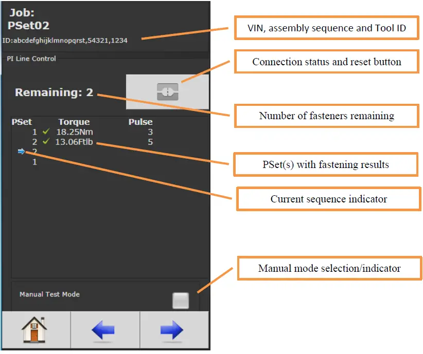
Once the serial port mode is set to PI Line Control, a new run screen will be available displaying VIN, assembly sequence, Tool ID, connection status, reset button, number of fasteners remaining, PSet(s) with fastening results, current sequence indicator, and manual mode selection/indicator.
- VIN, Assembly Sequence, and Tool ID: The status header on all run screens will contain part information from the PI control system.
- Connection Status: Connection status is indicated by icons for Connected and Disconnected. The Disconnected status icon can be pressed to reset communications.
- Fasteners Remaining: Displays the number of fasteners remaining for the part in the work station. The tool is disabled when it hits zero.
- PSet(s) with Fastening Results: Displays results as fastenings are completed for the current sequence.
- Current Sequence Indicator: Indicates the current sequence with an arrow that moves down the list of PSets as fastenings are completed. The indicator is removed after Notification of Normal Work Completion or Notification of Forced Work Completion.
Introduction
The Gen IV family of controllers fully support the PI line control protocol. Communication with the PI line control is accomplished through a serial connection (RS-232). This document describes the configuration and behavior of the controller while connected to the PI line control system.
Configuring the Controller
Serial Port
The PI line control system communicates with the controller via a standard serial port. The Gen IV controller need to be configured the same as the PI line controller.
- Serial “Port Mode” be set to “PI Line Control”
- Serial port “Baud” set to 9600
- Serial port “Data Bits” set to 8
- Serial port “Stop Bits” set to 1
- Serial port “Parity” set to “Odd”

Barcode Identifiers
When the part enters the work station the PI line control sends work instructions to the torque controller. This work instruct contains the following information.
- 5-digit assembly sequence number
- 20-digit VIN
- 4-digit Tool ID
- Sequence of parameter sets that are to be used on the part in the station.
Because the assembly sequence, VIN and Tool ID are different lengths they can all be stored in their own barcode ID. This allows the information to be displayed on the run screen and stored with each fastening result.
Configuring three masks in the barcode configuration to capture the different lengths will sort each to a unique identifier.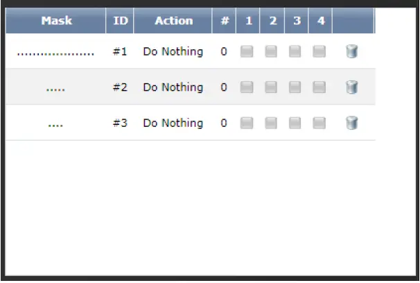
JOBS
- The use of JOBS is not recommended for controllers used in the PI Line Control environment.
PI Line Control Run Screen
Once the serial port mode is set to “PI Line Control” a new run screen will be available.
VIN Assembly Sequence and Tool ID
- The ID in the status header for all run screens will contain the part information from the PI control system.
Connection Status
The connection status is indicated by one of two icons.
 Connected
 Disconnected. When the Disconnected the status icon can be pressed to reset the communications.
Fasteners Remaining
- The number of fasteners remaining is for the part currently in the work station.
- It starts with the number of PSets that is to be ran and decrements by one for each acceptable fastening. When it hits zero the tool is disabled.
PSet(s) with Fastening Results
- As fastenings are completed the results are displayed for the current sequence.
Current Sequence Indicator
- The current sequence is indicated with an arrow. As acceptable fastenings are completed the indicator will move down the list of PSets.
- Once the PI control sends “Notification of Normal Work Completion” or “Notification of Forced Work Completion” the indicator is removed.
Manual Mode
Manual mode is used to enable the tool for testing. Entering manual mode will enable the tool, clear the PSet and results list. It will also clear the IDs (this will result in fastening results being stored without vehicle information). Fastening performed in manual mode will not be displayed on this run screen but can be observed on other screens. Manual mode is only allowed when a part is not in process. If a new work instruction is received from the PI control system, manual mode is canceled.
Run Screen Icons
While running the controller on the PI line control system the tool can be disabled for several reasons. Whenever it is disabled the run screen icon(s) and LED display will give the reason.
| Run Screen Stop Icon | LED Display | Reason |
 |
“DONE” | The list of PSets from the PI control has been completed |
 |
“PI” | There is a communication error to the PI line control system. |
 |
“PSET” | The active PSet does not match the PSet sent by the PI line control system. This can occur if the PSet number is changed contrary to the PI line control. |
Contact
- 9948 SE Oak Street Portland, OR 97216
- TEL: 800.852.1368
- FAX: 503.262.3410
- www.aimco-global.com
FAQ
- Q: Can I use JOBS with controllers in the PI Line Control environment?
- A: It is not recommended to use JOBS for controllers in the PI Line Control environment.
Documents / Resources
 |
AcraDyne GenIV Controller on PI Line Control Network [pdf] Owner's Manual GenIV Controller on PI Line Control Network, GenIV, Controller on PI Line Control Network, PI Line Control Network, Control Network, Network |