
TQ SU100 Sensor Unit Instruction Manual

Sensor Unit
Installation instructions
Edition 12/2024 EN
1. Scope
This document applies to the Sensor Unit SU100 series with LAN and/or RS485 communication interfaces.
The product variants of the SU100 series are named according to the number of current transformers included, for example:
SU103 refers to the SU100 with 3 current transformers.
These products are combined under the designation SU100.
2. Connection and set-up
At least the line conductor L1 and neutral conductor N must be connected since it is these conductors that power the SU100.

3. Intended use
The SU100 is a measuring device that measures electrical values at the point of connection and makes them available via LAN or RS485.
This product is NOT an active electrical energy meter as defined by EU Directive 2004/22/EC (MID); it must only be used for internal accounting purposes.
The data that the SU100 collects about the energy generated by your system may differ from the data from the main energy meter.
NOTICE
Devices which process the measured data from the SU100 must ensure that missing or incorrect measured values from the SU100 cannot cause a hazard.
As it is classified as overvoltage category III, the SU100 must only be connected in the sub-distribution board or consumer unit, downstream of the electricity supply company’s energy meter.
The SU100 is suitable for indoor use only.
The SU100 is approved for use in the EU Member States and the UK. Do not use the SU100 if it is damaged and then use only as described in this documentation. Any other use or the use of damaged units may result in injury or damage to property.
For safety reasons, the product (including the software) must NOT be modified and components must NOT be installed that are not expressly recommended or sold by TQ-Systems GmbH for this product. Any use of the product other than as described in the Intended use section shall be regarded as contrary to the intended use. Unauthorised changes, conversions or repairs and opening of the product are prohibited.
The enclosed documentation is part of the product and must be read, followed and then retained in a place that is accessible at all times.
4. Supported products and software versions
For information on the supported products, the individual functions of your preinstalled software and firmware updates, go to the SU100 product page at www.tq-automation.com.
5. Items supplied
SU10X
- 1× SU10X with LAN (L) and/or RS485 (R)
- 1× Installation manual
- 1× Software license
- 1× Power supply connector
- 2× RS485 connector – only for SU10X with LR or R
- X = 1…3:
1× CT connector
X× Current transformers (CT) or
1× EB103 - X = 4…6:
2× CT connectors
X× Current transformers (CT) or
2× EB103 - Possible CT variants:
63 A, 100 A, 200 A, 600 A
6. Safety instructions
DANGER
Danger of death by electric shock.
Live components carry potentially fatal voltages.
- Only use the SU100 in a dry environment and keep it away from liquids.
- Install the SU100 only in approved enclosures or distribution boards downstream of the electricity supply company’s meter so that the connections for the line and neutral conductors are located behind a cover or guard to prevent accidental contact.
- The enclosure or distribution board must be accessible only with a key or suitable tool in order to limit access to authorised personnel.
- Before starting any installation or maintenance work, switch off the power to the distribution board and secure to prevent it being switched on again accidentally.
- Before cleaning, switch off the power to the SU100 and only use a dry cloth to clean.
- Maintain the prescribed minimum distances between the network cable and mains voltage installation components or use suitable insulation.
NOTICE
Damage to or destruction of the SU100 by voltage surges on the data cable (Ethernet, RS485)
— If data cables are installed outside the building, voltage surges can be caused by lightning strike, for example.
— If installed outside the building, the data cable and remote station (inverter, charging station, etc.) must be protected with suitable over voltage protection.
Damage to or destruction of the SU100 by improper use
— Do not operate the SU100 outside the specified technical tolerances.
7. Technical data


8. Product description


9. Installation
9.1. Assembly
To fit the SU100, hook the device over the top edge of the DIN rail and press it until it clicks into place.
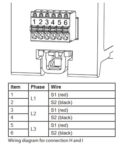
9.2. Connection diagram
(Illustration example SU103 with 3 current transformers)

9.3. Current inputs and transformers
1. Only use the current transformers provided.
2. Connect the current transformer to the device first and then to the conductor.
3. Connect the current transformer cables as shown in the following connection diagram/scheme.
4. Open the current transformer for L1 in order to insert the wire, then close again until you hear it click into place. Repeat this step for all necessary phases. Note the direction of the arrows! See “9.2. Connection diagram”.
9.4. Voltage inputs
1. Connect the required cables L1, L2, L3, N to the SU100.
2. Permitted cable cross-sections: 0.20 … 2.50 mm²

The end user must be able to isolate the SU100 from the power supply by means of a freely accessible meter fuse or an additional circuit-breaker.
NOTICE
Check correct assignment of the phases
- Make sure that the phases are all correctly allocated, otherwise the SU100 will return incorrect measured values.
- The voltage inputs of the SU100 [L1, L2, L3] must be protected with 16 A type B fuses.
9.5. RS485 interface
The SU100 has an RS485 interface; its two connections allow it to be daisy-chained to other devices.
Note the following points when connecting external devices to the RS485 interface of the SU100:
Requirement for the cable:
— Nominal voltage/wire insulation: 300 V RMS
— Cable cross section: 0.20 … 0.50 mm²
— Max. cable length: 100 m
— Cable type: Rigid or flexible
— Recommendation: use standard cable, e.g. AlphaWire, designation 2466C.
Alternatively, a CAT5e cable can also be used.
Requirement for cable installation:
- In the area for connecting the RS485 interface on the SU100, mechanical means must be provided to ensure that individual wires of the connecting cable are at least 10 mm away from live parts.
- The connecting cable must be run separately from the mains cables in the distribution board and on the permanent link.
Requirements for the remote station:
— The RS485 interface of the connected device must meet the safety extra low voltage requirements.

10. LED statuses


11. Set-up
11.1. Set-up
1. Install the SU100 as described in section “9. Installation”.
2. Attach the cover or the contact guard of the sub-distribution board to the SU100.
3. Restore the power to the sub-distribution board.
4. When the set-up is complete, the status LED lights up green and stays on.
11.2. LAN connection
1. Connect the network cable to the network connection of the SU100.
2. Connect the other end of the network cable to a router/switch or directly to the PC/laptop.
3. When the connection is successful and the remote station is active, the network LED lights up green.
11.3. RS485 connection
1. Connect the RS485 interface as described in section “9.5. RS485 interface”.
2. When the connection is successful and the remote station is active, the serial bus LED lights up green.
12. Operation
12.1. Restore the SU100 factory settings
Use a pointed object to press the button as follows:
— 1× short (0.5 second)
— Then, within 1 second, 1× long (between 3 seconds and 5 seconds)
— If this is done successfully, the status LED flashes orange twice
12.2. Restart the SU100
Use a pointed object to press the button for at least 10 seconds.
12.3. Firmware update
To activate the website for the firmware update, hold down the button until the status LED flashes green.
You can then open the website in your browser.
13. Fault finding
13.1. The status LED does not light up.
The SU100 is not being supplied with power.
— Make sure that at least the line conductor
L1 and the neutral conductor N are connected to the SU100.
13.2. The status LED lights up red permanently.
An error has occurred.
- Restart the SU100 (see section “12.2. Restart the SU100”).
- Please contact your service engineer or installation engineer.
13.3. The network LED does not light up or the SU100 is not found on the network.
The network cable is not plugged into the network connection correctly.
- Make sure that the network cable is plugged into the network connection correctly.
The SU100 is not on the same local area network. - Connect the SU100 to the same router/ switch.
13.4. The SU100 returns unrealistic measured values.
Check the following points:
- Voltages connected at L1, L2, L3, N.
- Assignment of current transformers to the phases: does CT L1 also measure current for phase L1?
- Current transformer connected in correct direction. See section “9.2. Connection diagram”.
- Check whether the current transformers are correctly configured via Modbus.
14. Environmentally-friendly disposal
![]() Dispose of the SU100 in accordance with the electronic waste disposal regulations that apply on site.
Dispose of the SU100 in accordance with the electronic waste disposal regulations that apply on site.
15. Contact
If you have technical problems, please contact your service engineer or installation engineer.
15.1. Manufacturer
TQ-Systems GmbH | TQ-Automation
Mühlstraße 2
82229 Seefeld | Germany
Phone +49 8153 9308-688
support@tq-automation.com
www.tq-automation.com
© TQ-Systems GmbH 2024 | All data is for information only | Subject to change without prior notice | AUT_Installationsanleitung_SU100_EN_Rev0105
Read More About This Manual & Download PDF:
Documents / Resources
 |
TQ SU100 Sensor Unit [pdf] Instruction Manual SU100, SU103, SU100 Sensor Unit, SU100, Sensor Unit, Unit |


