850G-10PWI Industrial Ethernet Switch Quick Installation Guide
Version: 1.00
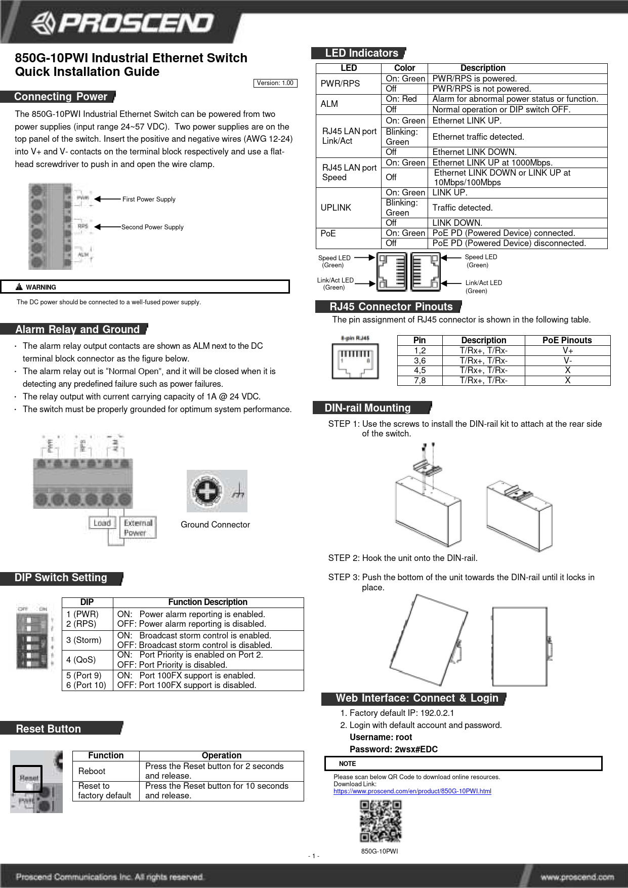
Connecting Power
The 850G-10PWI Industrial Ethernet Switch can be powered from two power supplies (input range 24~57 VDC). Two power supplies are located on the top panel of the switch. Insert the positive and negative wires (AWG 12-24) into the V+ and V- contacts on the terminal block respectively and use a flat-head screwdriver to push in and open the wire clamp.
Power Terminal Block Diagram: Depicts a terminal block with labels PWR and RPS for two power supplies, each with '+' and '-' contacts. An ALM (Alarm) terminal is also shown. Below these are connectors labeled 'Load' and 'External Power'. Arrows indicate 'First Power Supply' connected to PWR and 'Second Power Supply' connected to RPS.
⚠️ WARNING: The DC power should be connected to a well-fused power supply.
Alarm Relay and Ground
The alarm relay output contacts are shown as ALM next to the DC terminal block connector. The alarm relay is "Normal Open" and will close when detecting any predefined failure, such as power failures. The relay output has a current carrying capacity of 1A @ 24 VDC. The switch must be properly grounded for optimum system performance.
Ground Connector Symbol: A standard electrical ground symbol, consisting of a circle with a cross inside, connected to a line with three progressively shorter horizontal lines.
LED Indicators
| LED | Color | Description |
|---|---|---|
| PWR/RPS | On: Green Off | PWR/RPS is powered. PWR/RPS is not powered. |
| ALM | On: Red Off | Alarm for abnormal power status or function. Normal operation or DIP switch OFF. |
| RJ45 LAN port Link/Act | On: Green | Ethernet LINK UP. |
| Blinking: Green Off | Ethernet traffic detected. Ethernet LINK DOWN. | |
| RJ45 LAN port Speed | On: Green | Ethernet LINK UP at 1000Mbps. |
| Off | Ethernet LINK DOWN or LINK UP at 10Mbps/100Mbps. | |
| UPLINK | On: Green | LINK UP. |
| Blinking: Green Off | Traffic detected. LINK DOWN. | |
| PoE | On: Green | PoE PD (Powered Device) connected. |
| Off | PoE PD (Powered Device) disconnected. |
RJ45 Port LED Diagram: Illustration of two RJ45 ports, each with a 'Speed LED (Green)' and a 'Link/Act LED (Green)'.
RJ45 Connector Pinouts
The pin assignment of the RJ45 connector is shown in the following table.
RJ45 Connector Diagram: A visual representation of an 8-pin RJ45 connector, with pins numbered 1 through 8.
| Pin | Description | PoE Pinouts |
|---|---|---|
| 1,2 | T/Rx+, T/Rx- | V+ |
| 3,6 | T/Rx+, T/Rx- | V- |
| 4,5 | T/Rx+, T/Rx- | X |
| 7,8 | T/Rx+, T/Rx- | X |
DIN-rail Mounting
Follow these steps to mount the switch using a DIN-rail kit:
- STEP 1: Use the screws to install the DIN-rail kit to attach at the rear side of the switch.
- STEP 2: Hook the unit onto the DIN-rail.
- STEP 3: Push the bottom of the unit towards the DIN-rail until it locks in place.
DIN-rail Mounting Diagrams: A sequence of illustrations depicting the DIN-rail mounting process: attaching the bracket to the switch, hooking the switch onto the rail, and securing it.
DIP Switch Setting
DIP Switch Diagram: An illustration of a block of six DIP switches, numbered 1 to 6. Each switch is shown with its 'OFF' and 'ON' positions clearly marked.
| DIP | Function Description |
|---|---|
| 1 (PWR) | ON: Power alarm reporting is enabled. OFF: Power alarm reporting is disabled. |
| 2 (RPS) | ON: Broadcast storm control is enabled. OFF: Broadcast storm control is disabled. |
| 3 (Storm) | ON: Broadcast storm control is enabled. OFF: Broadcast storm control is disabled. |
| 4 (QoS) | ON: Port Priority is enabled on Port 2. OFF: Port Priority is disabled. |
| 5 (Port 9) | ON: Port 100FX support is enabled. OFF: Port 100FX support is disabled. |
| 6 (Port 10) | ON: Port 100FX support is enabled. OFF: Port 100FX support is disabled. |
Web Interface: Connect & Login
- Factory default IP: 192.0.2.1
- Login with default account and password.
Username: root
Password: 2wsx#EDC
NOTE: Please scan below QR Code to download online resources.
Download Link: https://www.proscend.com/en/product/850G-10PWI.html