GIRA Information and Blanking Modules
Product Information and Installation Guide
GIRA Company Information
Gira Giersiepen GmbH & Co. KG
Elektro-Installations-Systeme
Industriegebiet Mermbach, Dahlienstraße
42477 Radevormwald
Postfach 1220, 42461 Radevormwald
Tel: +49 (0) 21 95 - 602 - 0
Fax: +49 (0) 21 95 - 602 - 191
Website: www.gira.de
Email: info@gira.de
Product Overview
This document details GIRA's Information Module and Blanking Module, designed for use with System 106 and various mounting housings.
Information Module
The Information Module displays information, such as house numbers, and can be personalized via the GIRA labeling service at www.beschriftung.gira.de.
Blanking Module
The Blanking Module serves as a placeholder for future applications, like camera modules, and enhances the design of larger door stations within the system.
Module Mounting Instructions
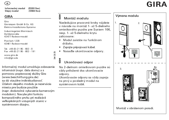
ℹ️ Module Mounting
Refer to the instructions for mounting the surface-mounted housing (1–5 units) or the flush-mounted housing with System 106 (1–5 units) for the following steps:
- Secure the module onto the functional carrier.
- Connect the connecting cable.
- Adjust the load resistors.
Diagram Descriptions
Diagram 1: Shows a single module.
Diagram 2: Depicts a module being attached to a housing, with a close-up of the connecting cable. An arrow indicates the direction of attachment.
Diagram 3: Illustrates a multi-module housing with two load resistors connected to the first and last modules. The text '4x' indicates four screws are used for mounting.
The accompanying text states: "Mounting in reverse order."
Load Resistor Information
ℹ️ Load Resistor
For 2-unit surface-mounted housings and above, two load resistors are always included.
Load resistors must be connected to the first and last modules on the system cable.
Product Details
Model Numbers: (5560 9xx), (5568 9xx)
Document Reference: 34/2025