QIACHIP Smart Switch User Manual
Models: KR2201G / KR2201GS
Important Safety Warnings
- This device is for indoor use only.
- This device should not be exposed to dripping or any liquid sources.
- This device should only be installed by adults.
- Do not install near any heat sources.
- Do not use this device with dimmers.
- Do not use this device in a fully enclosed fixture.
- Pay attention to electricity and do not use it in humid places.
- If the unit is heavier than the replacement unit, it may reduce the stability of some fixtures and affect the contacts.
Wiring Diagrams
The following diagrams illustrate the wiring for different models and configurations.
KR2201G/KR2201GS Wiring Diagram
This diagram shows the general wiring for both models. The QIACHIP Smart Switch has 'OUT' and 'IN' terminals. 'IN' connects to the power source (L: Live, N: Neutral), and 'OUT' connects to the load (L: Live, N: Neutral). The diagram also shows a remote control with buttons labeled 'A' and 'B', and indicates AC 90V-250V input.
KR2201G: Remote Control Only Wiring
For the KR2201G model, wiring is shown connecting the power source (L, N) to the 'IN' terminals and the load (L, N) to the 'OUT' terminals. This model is controlled exclusively by remote control.
KR2201GS: Remote Control Wiring Method
The KR2201GS can be wired for remote control. The diagram shows 'IN' terminals for power (L, N), 'OUT' terminals for the load (L, N), and an additional 'S' terminal. The 'S' terminal is not used in this configuration for remote-only control.
KR2201GS: Wiring for Simultaneous Use of Remote Control and External Switch
This configuration for the KR2201GS allows control via both remote and an external wall switch. The 'IN' terminals connect to power (L, N), the 'OUT' terminals connect to the load (L, N), and the 'S' terminal connects to the external switch. The diagram shows the external switch connected to the 'S' terminal and the neutral line (N) of the power source.
Remote Control and External Switch
Illustrations show a typical remote control with buttons A and B, and a standard wall-mounted external switch.
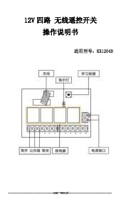
Wireless Remote Control Function Operation Instructions (Applicable Models: KR2201G/KR2201GS)
The smart switch can be paired with a remote control. The pairing process involves using a button on the smart switch, often referred to as the "Smart Circuit Breaker Pairing Button" (indicated by a red dotted circle in a diagram).
Toggle Mode Setting Description
In Toggle Mode, pressing the remote control turns the device on, and pressing it again turns it off.
Setting Method:
- Press the setting button on the "Smart switch" twice.
- The red indicator light will flash and then light up.
- Press the button on the remote control that you want to pair.
- When the red indicator light flashes and goes out, the toggle mode setting is successful.
Latch Mode Setting Description
In Latch Mode, one button turns the device ON, and another button turns it OFF.
Setting Method:
- Press the code button on the "Smart switch" 3 times.
- The red indicator light will flash and then light up.
- Press the function key that is set to turn on (e.g., button ON).
- Then press the desired function key to turn off (e.g., button OFF).
- The red indicator light will flash to confirm that the latch mode is successfully set.
Push Button Mode Setting Description
In Push Button Mode, the device stays on or off only while the button is pressed.
Setting Method:
- Press the code Setting button on the "Smart switch" 4 times.
- The red indicator light flashes on the remote control.
- When the red indicator light flashes and then goes out, the push button mode is set successfully.
External Switch Instructions (Applicable Models: KR2201GS)
The KR2201GS supports control via an external switch, which can also be used for pairing.
External Switch Support Type: Toggle Switch
Reset Settings
This action erases all paired remote control data.
Method:
- Connect the KR2201GS to the power supply and lamp.
- Press the external switch 8 times in a row.
- The light will flash 3 times before turning off.
- Reset is complete, and all remote control data is erased.
External Switch Mode Description
The KR2201GS can be controlled using an external switch or a remote control. The external switch is used to put the KR2201GS into the remote control learning state.
Toggle Mode Setting Description (using external switch):
- Connect the power and the light.
- Press the external switch five times in a row.
- The light will flash three times and stay on, indicating pairing mode.
- Within 5 seconds, press the corresponding button on the remote control to pair.
- The light will turn off when pairing is complete. (If no pairing occurs within 5 seconds, the load will remain connected and exit pairing mode.)
Latch Mode Setting Description (using external switch)
Method:
- Connect the power and the light.
- Press the external switch 6 times.
- The light will flash 3 times and then stay on, indicating that it has entered the pairing mode.
- Within 5 seconds, press the button on the remote control that you want to set as the "ON" button (e.g., Button A). The load will disconnect and reconnect 3 times, and then stay connected.
- Next, press the button on the remote control that you want to set as the "OFF" button (e.g., Button B). The load will disconnect and reconnect 3 times, and then turn off.
- If no pairing occurs within 5 seconds, the load will remain connected and exit the pairing mode.
External Switch Reset Settings
Make the load on or the load is already on, then press the external switch 8 times continuously. At this time, the...
(Note: The OCR text for this section appears to be incomplete.)