12V DC Motor Forward/Reverse Controller Operation Manual
Product Wiring Instructions
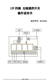
DC Motor Forward/Reverse Wiring Diagram
Connection Terminals:
- M1: Connect to Motor
- M2: Connect to Motor
- +V: Power Positive
- GND: Power Negative
Please do not connect wires while the power is on.
Diagram Description: The diagram shows a receiver board with terminals labeled M2, M1, +V, and GND. Wires from a DC motor are connected to M1 and M2. Wires from a DC power source (12V) are connected to +V and GND.
Function Description and Setting Method
Note: All working modes require QIACHIP brand remote controls (transmitters) and controllers (receivers/wireless remote control switches). Compatibility with other brands is not guaranteed.
Reset Function:
Clears all paired remote controls. When the receiver's data is cleared, all remote controls will be unable to operate the receiver.
Settings Reset:
Press the receiver's learning button 8 times. The receiver will clear all remote control data from its memory. The reset is complete when the receiver's LED finishes flashing.
Description of the Three Working Modes:
This wireless remote control switch has 3 working modes: Momentary (Jog), Toggle (Self-locking), and Latching (Interlocking).
Momentary Mode (Jog):
After successful pairing, press and hold a remote button (e.g., A) for forward motor rotation. Release the button to stop the motor. Press and hold another button (e.g., B) for reverse motor rotation. Release the button to stop the motor.
Toggle Mode (Self-locking):
After successful pairing, press a remote button (e.g., A) to rotate the motor forward. Press the same button again to stop the motor. Press another button (e.g., B) to rotate the motor in reverse. Press the same button again to stop the motor.
Latching Mode (Interlocking):
After successful pairing, press a remote button (e.g., A) for forward motor rotation. Press another remote button (e.g., B) for reverse motor rotation. Press a third remote button (e.g., C) to turn off the motor. (Note: This mode is recommended for three or four-button remote controls).
How to Set the Working Mode of the Switch Controller:
Note: The working mode can only be set when the LED is off.
Set Momentary Mode:
- Press the receiver's learning button once. The receiver's LED will turn off, entering the setting state.
- Press a button on the remote control (e.g., button A) once. The receiver's LED will flash and then turn off.
- Press another button (e.g., button B) on the same remote control. The indicator will flash and then light up, indicating successful setting of Jog mode.
Set Toggle Mode:
- Press the receiver's learning button twice. The receiver's LED will turn off, entering the setting state.
- Press a button on the remote control (e.g., button A) once. The receiver's LED will flash and then turn off.
- Press another button (e.g., button B) on the same remote control. The indicator will flash and then light up, indicating successful setting of Toggle mode.
Set Latching Mode:
- Press the receiver's learning button 3 times. The receiver's LED will turn off, entering the setting state.
- Press a button on the remote control (e.g., button A) once. The receiver's LED will flash and then turn off.
- Press another button (e.g., button B) on the same remote control. The indicator will flash and then light up, indicating successful setting of Latching mode.
Precautions
- Replace the remote control battery promptly when its voltage is low (indicated by a reduced remote control distance).
- When using wireless electronic products, avoid areas with strong interference sources such as metal shields, large electronic equipment, and electromagnetic fields to prevent short remote control distances or malfunction. Do not use this electronic product abnormally, as it can reduce product performance and lifespan, potentially damage the product, and pose safety risks.
Product Parameters
| Parameter | Value |
|---|---|
| Working Voltage | DC12V |
| Working Frequency | 433.92MHz |
| Standby Current | 8mA |
| Pairing Method | Learning button |
| Receiver Sensitivity | -105dBm |
| Working Mode | Momentary, Toggle, Latching |
| Support Encoding Chip | Learning Code (1527) |
| Wiring Terminal Description | M1, M2 (Connect to motor), +V (Power positive), GND (Power negative) |
| Working Temperature | -10°C ~ +70°C |
| Size | 35 * 30 * 18 (mm) |
For more services, please visit the official website: https://www.qiachip.com