12V 4-Channel Receiver Instruction
Module: KR1204B
Product Overview
This document provides instructions for the QIACHIP 12V 4-Channel Wireless Remote Control Receiver, module KR1204B. It details wiring diagrams, function descriptions, setting methods for various operating modes, and technical specifications.
Wiring Diagrams
*Please Don't install with electricity
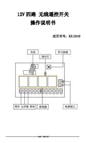
Receiver Layout Diagram
The receiver unit features the following components:
- Antenna: For receiving wireless signals.
- Indicator: An LED light for status indication.
- Learning Button: Used for pairing remote controls with the receiver.
- Relay Terminals: Marked 1 through 12. Terminals 1-4 are associated with Relay 1, 5-6 with Relay 2, 7-8 with Relay 3, and 9-10 with Relay 4. Terminals 11 and 12 are for power input (+V and GND respectively).
- NO, COM, NC: Normally Open, Common, and Normally Closed output terminals for each relay.
- Power Supply: Connection terminals labeled +V and GND for the receiver's power input.
DC Lamp Wiring Diagram
This diagram illustrates the connection of up to four DC lamps (labeled Load1, Load2, Load3, Load4) to the receiver. Each load is connected to the corresponding relay's output terminals (NO, COM, NC) and the DC power supply. The receiver itself is powered via DC12V+ and DC12V- terminals.
Wiring Diagram of Two DC Motors
This diagram shows the wiring configuration for two DC motors (labeled M1 and M2). Each motor is connected to the receiver's relay output terminals (e.g., terminals 1-4 for motor 1, terminals 5-8 for motor 2) and the DC power supply. The receiver is powered by DC12V+ and DC12V- terminals.
Function Description and Setting Method
Note: All the following working modes need to be implemented with a QIACHIP brand remote control (transmitter) and the controller (receiver / wireless remote control switch). There is no guarantee that remote controls from other brands will work properly.
Reset Function
This function clears all matched remotes. When the data is cleared, previously paired remote controls will no longer be able to operate the receiver.
Settings Reset
To perform a settings reset: Press the receiver's learning button 8 times. The receiver will clear all remote control data stored in its memory. When the receiver's LED flashes, the reset function is complete.
Description of the Three Working Modes
The receiver supports three primary working modes:
- 1) Momentary Mode: After successful pairing, pressing and holding the remote control button (e.g., button A) turns the corresponding relay on. Releasing the button turns the corresponding relay off.
- 2) Toggle Mode: After successful pairing, pressing the remote control button (e.g., button A) once turns the corresponding relay on. Pressing the same button again turns the corresponding relay off.
- 3) Latching Mode: After successful pairing, pressing remote control button A turns the corresponding relay (Relay A) on. Pressing remote control button B turns Relay A off and Relay B on. Pressing both remote control buttons A and B simultaneously turns all relays off.
How to Set the Working Mode of the Switch Controller
Note: The working mode can only be set when the LED indicators of the switch controller are lit.
Set Momentary Mode (Jog):
- Press the receiver's learning button once.
- Wait for the LED on the receiver to light up and enter the setting state.
- Press the button on the remote control (e.g., button A) once. The LED on the receiver will flash and then turn off. The jog mode is set successfully.
Set Toggle Mode:
- Press the learning button on the receiver twice.
- Wait for the LED on the receiver to light up and enter the setting state.
- Press the button on the remote control (e.g., button A) once. The LED indicator on the receiver will flash and then turn off. The self-locking mode (Toggle) is set successfully.
Set Latching Mode:
- Press the learning button on the receiver 3 times.
- Wait for the LED on the receiver to light up and enter the setting state.
- Press the button on the remote control (such as button A) once. The LED on the receiver will flash and then turn off, and the interlock mode (Latching) is set successfully.
Technical Data
| Parameter | Value |
|---|---|
| Input Power | DC 6V-30V |
| RF Frequency | 433.92MHz |
| Standby Current | 5mA |
| Load Power | 120W × 4 |
| Match Way | Learning button |
| Receiver Sensitivity | -104dbm |
| Operation Mode | Momentary, Toggle, Latching |
| Output | NO, NC, COM |
| Support Encoding Chip | Learning Code(1527) |
| Modulation Mode | ASK |
| Maximum of pairing remote | No more than 20 pcs |
| Working Temperature | -10 ~ +80°C |
| Size | 73x55x30 mm |
Further Information
For more services, please check our website: www.qiachip.com