![]() GRID485-MB Modbus TCP to Modbus RTU
GRID485-MB Modbus TCP to Modbus RTU
User Guide
GRID485-MB Modbus TCP to Modbus RTU
Copyright and Trademark
Copyright © 2024, Grid Connect, Inc. All rights reserved.
No part of this manual may be reproduced or transmitted in any form for any purpose other than the purchaser’s personal use, without the express written permission of Grid Connect, Inc. Grid Connect, Inc. has made every effort to provide complete details about the product in this manual, but makes no warranty of any kind with regard to this material, including, but not limited to, the implied warranties of merchantability or fitness for a particular purpose. In no event shall Grid Connect, Inc. be liable for any incidental, special, indirect, or consequential damages whatsoever included but not limited to lost profits arising out of errors or omissions in this manual or the information contained herein.
Grid Connect, Inc. products are not designed, intended, authorized or warranted for use as components in systems intended for surgical implant into the body, or in other applications intended to support or sustain life, or in any other application in which the failure of a Grid Connect, Inc. product could create a situation where personal injury, death, or severe property or environmental damage may occur. Grid Connect, Inc. reserves the right to discontinue or make changes to its products at any time without notice.
Grid Connect and the Grid Connect logo, and combinations thereof are registered trademarks of Grid Connect, Inc. All other product names, company names, logos or other designations mentioned herein are trademarks of their respective owners.
GRID485™, GRID45™ and gridconnect© are trademarks of Grid Connect, Inc.
Grid Connect Inc.
1630 W. Diehl Rd.
Naperville, IL 60563, USA
Phone: 630.245.1445
Technical Support
Phone: 630.245.1445
Fax: 630.245.1717
On-line: www.gridconnect.com
Disclaimer
Operation of this equipment in a residential area is likely to cause interference in which case the user, at his or her own expense, will be required to take whatever measures may be required to correct the interference.
Attention: This product has been designed to comply with the limits for a Class B digital device pursuant to Part 15 of FCC Rules. These limits are designed to provide reasonable protection against harmful interference in a residential installation. This equipment generates, uses, and can radiate radio frequency energy, and if not installed and used in accordance with this guide, may cause harmful interference to radio communications.
Changes or modifications to this device not explicitly approved by Grid Connect will void the user’s authority to operate this device.
The information in this guide may change without notice. The manufacturer assumes no responsibility for any errors that may appear in this guide.
OVERVIEW
Introduction
The GRID485 is an RS422/485 serial to network converter device. The network interfaces are wired Ethernet and WiFi wireless Ethernet. GRID485 is the updated version of our popular NET485. The GRID485 is named after the NET485 but is based on the new high performance GRID45 all in one intelligent RJ45 connector. The firmware in the device determines the network protocols for accessing the serial information from the RS422/485 device(s). The possible network protocols include simple TCP/IP bridging and industrial protocols like Modbus TCP, EtherNet/IP, BACnet IP and others.
The RS422/485 side can connect to serial devices over long distances (up to 4,000 ft.). The GRID485 supports RS485 in 2-wire mode (half-duplex) or in 4-wire mode (full-duplex). The half-duplex or full-duplex operation is chosen in the device configuration. RS485 4-wire mode is often referred to as RS422, although this is not strictly accurate. For the remainder of the document we will only use RS485 to describe the serial interface of the GRID485. Using RS485 you can connect the GRID485’s serial interface to multiple devices in a RS485 multidrop bus.
The Wi-Fi interface supports a SoftAP for easy wireless configuration. A Web Manager provides a browserbased configuration and diagnostic tool. Configuration and device status can also be accessed via the setup menu through the serial line or a network port. The unit’s configuration is stored in nonvolatile memory and is retained without power.
Additional Documentation
The following guides are available for download on the internet.
| Title | Description and Location |
| GRID45 Modbus User Guide | Document providing Quick Start instructions and describing the Modbus firmware configuration and operation. www.gridconnect.com |
| GRID45 Serial Tunnel User Guide | Document providing Quick Start instructions and describing the serial tunnel firmware configuration and operation. www.gridconnect.com |
Technical Specifications
The transceiver used in the NET485 is intended for balanced data transmission and complies with both EIA.
Standards RS-485 and RS-422. It contains a differential line driver and a differential line receiver, and is suitable for half-duplex transfer. The input impedance is 19KOhm allowing up to 50 transceivers to be connected on the bus.
| Category | Description |
| CPU | 32-bit microprocessor |
| Firmware | Upgradeable via HTTP |
| Serial Interface | RS485/422. Baudrate software selectable (300 to 921600) |
| Serial Line Formats | 7 or 8 data bits, 1-2 Stop bits, Parity: odd, even, none |
| Ethernet Interface | IEEE802.3/802.3u, 10Base-T or 100Base-TX (Auto-sensing, Auto-MDIX), RJ45 |
| Wifi interface | 802.11 b/g/n, 2.4 GHz, Client Station and SoftAP, PCB antenna standard |
| Protocols Supported | IPv4, ARP, UDP, TCP, Telnet, ICMP, DHCP, BOOTP, Auto IP, and HTTP. Optional industrial protocols. |
| Power Input | 8VDC to 24VDC, approximately 2.5 W. |
| LEDs | 10Base-T & 100Base-TX Activity, Full/half duplex. |
| Management | Internal web server, Telnet login, HTTP |
| Security | Password protection |
| Internal Web Server | Serves configuration and diagnostic web pages |
| Weight | 1.8oz |
| Dimensions | 2.9×1.7×0.83 in (74.5x43x21 mm) |
| Material | Case: Flame Retardant |
| Temperature | Operating range: -30°C to +60°C (-22°F to 140°F) |
| Relative Humidity | Operating: 5% to 95% non-condensing |
| Warranty | 1-year limited warranty |
| Included Software | WindowsTM/Mac/Linux based Device Manager tool |
| UL Certification E357346-A1 | IEC 62368-1:2018 |
Hardware Description
The GRID485 has a 7-pin removable Phoenix connector for wiring power and RS485 communication lines.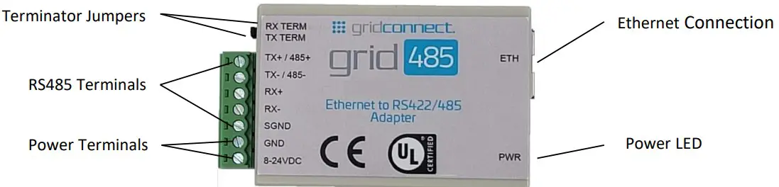
| GRID485 Signal | 7-Pin Phoenix |
| TX+ / 485+ | 7 |
| TX- / 485- | 6 |
| RX+ | 5 |
| RX- | 4 |
| SGND | 3 |
| GND | 2 |
| 8-24VDC | 1 |
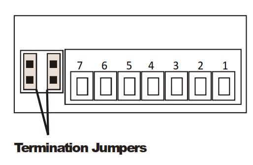
WARNING: Termination jumpers must be installed vertically.
Note: Do NOT use RX Term and TX Term jumpers on short transmission lines. Remove these jumpers to remove the 120 Ohm resistors from the transmit and receive lines.
Ethernet Connection
The GRID485 has an RJ45 Ethernet connector that supports 10/100 Mbps Ethernet. There are 2 status LEDs for indicating the status of the network connection.
The following table describes the LED functionality for the wired Ethernet connection
| Left LED Orange | Right LED Green | State Description |
| Off | Off | No Link |
| Off | On | 10 Mbps link, no activity |
| Off | Blinking | 10 Mbps link, with network activity |
| On | On | 100 Mbps link, no activity |
| On | Blinking | 100 Mbps link, with network activity |
Power Supply
Wire power to the GRID485 using the GND and 8-24VDC terminals.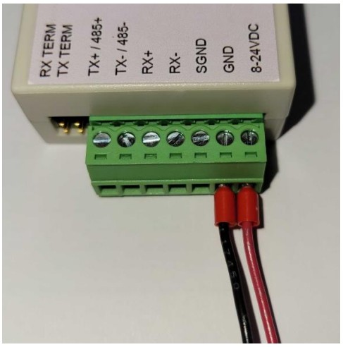
The GRID485 can use a DC power source from 8-24VDC. The current draw is determined by network activity and serial port communications. In general, a 2.5W supply will handle the load.
Most modular power supplies use the same method of designating which lead is positive and which one is negative. Generally, the lead with a white stripe, or white markings, is the positive lead. Verify the lead markings with a meter before connecting a power source to the GRID485.
Connect the positive lead to the terminal marked 8-24VDC. Connect the negative lead to the terminal marked GND. The power LED will come on when power is supplied.
RS485 Connections
The GRID485 has jumper terminals for adding a 120 Ohm termination resistor to the TX/485 and to the RX lines. Add these jumpers ONLY if you have long transmission lines and termination resistors are needed.
Termination should be made only at the ends of the RS485 bus.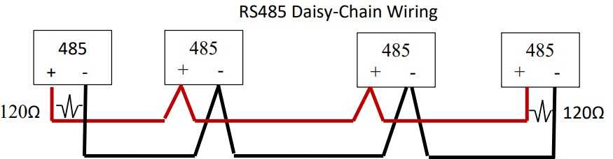 RS485 2-wire connections – for 2-wire half-duplex you will only need to wire to the 485+ and 485- terminals.
Make sure to match wire polarity when wiring to other RS485 devices. Be sure the GRID485 configuration is also set for half-duplex. In some installations and with longer cable runs you may need to add a 3 rd wire for Signal Ground (SGND) and termination (TX TERM side only) may be needed as well.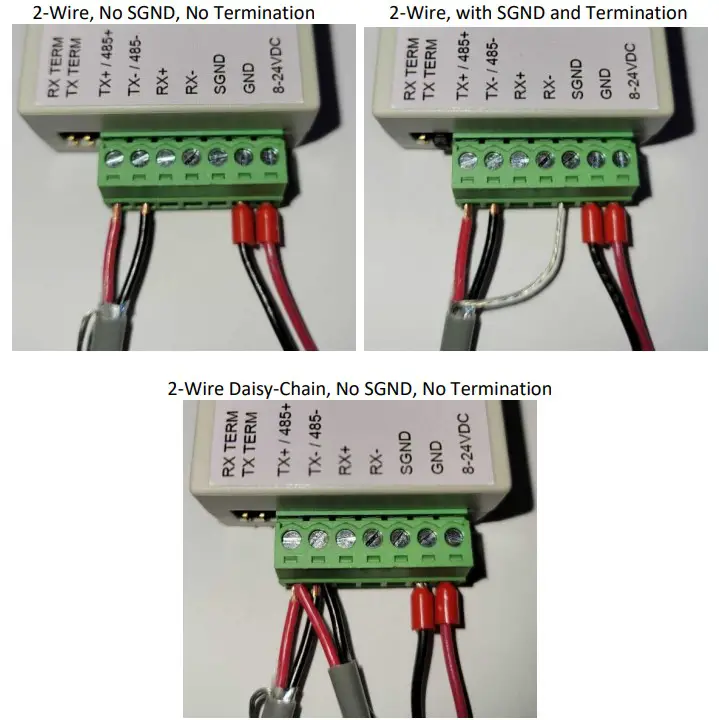 RS485 4-wire connections – for 4-wire full-duplex you will need to wire one pair to the TX+ and TX-terminals and wire the other pair to the RX+ and RX- terminals. Make sure to match polarities when wiring to other RS422/485 devices. The TX pair of the GRID485 should be wired to the RX pair of the other devices. The RX pair of the GRID485 can be wired to the TX pair of multiple RS485 devices or only one RS422 device. Be sure the GRID485 configuration is also set for full-duplex.
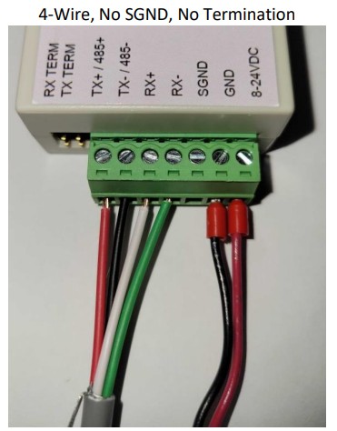
Mounting option
The GRID485 can be purchased with a Surface Mount Strap or a DIN Rail Clip & Strap. The Surface Mount Strap alone can be used to mount the GRID485 to a flat surface. With the additional DIN Rail Clip the GRID485 can be mounted on a DIN rail in several different orientations.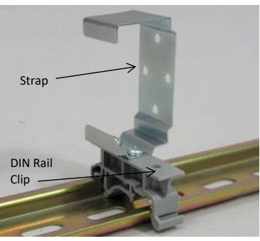
QUICK START
Follow these general instructions to get your unit up and running fast. The screen shots are taken from the Modbus TCP firmware, but the steps are similar for all firmware types. Refer to the user guide for your exact GRID485 firmware type for specific instructions.
You must first establish a network connection to the unit. This can initially be done using the wired Ethernet port or using the Wi-Fi interface. The configuration is done via an Internet browser. Once the network connection is established, the browser can be used to login to the unit directly and perform configuration.
To start with a Wi-Fi connection jump to the section on Wi-Fi Setup.
Ethernet Setup
The following sections will detail the steps for basic setup of the GRID485 device over Ethernet.
- Connect an Ethernet cable for your network to the RJ45 port.
- Connect power to the GRID485 device.
By default, the GRID485 device will attempt to get its network parameters for the Ethernet interface from a local DHCP server.
Finding the device on the network
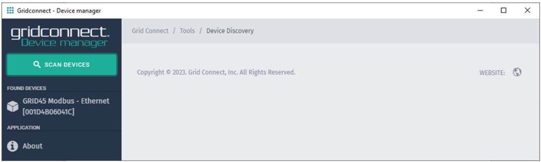
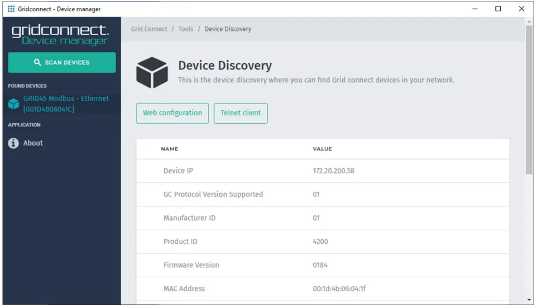
- Run the Grid Connect Device Manager software on a PC to find the GRID485 device on the network and etermine its IP address which was assigned by your network’s DHCP server. If you have not yet installed the Device Manager software you can download the installer from www.gridconnect.com
- Upon launch, Device Manager will search for GRID45 series devices on the network. Select the GRID45 module from the found devices on the local network with the matching MAC address to the GRID485. (You may also click on the Scan Devices icon if your device isn’t found immediately.)
- Note the device IP address.
- Access Web configuration by entering the device IP address in the address bar of a browser or clicking on the Web configuration icon in the Device manager. Proceed to the later section on GRID485 Web Configuration.
Wi-Fi Setup
The following sections will detail the steps for basic setup of the GRID485 device over Wi-Fi.
- The GRID485 has an internal PCB antenna.
- Connect power to the GRID485 device.
Finding the wireless SSID
By default, the Soft AP mode is enabled with a SSID of GRID45ppp_xxxxxx, where ppp is a protocol designation and xxxxxx are the last six hex digits of the unique GRID485 MAC address. An SSID of GRID45MB_xxxxxx is used when Modbus TCP firmware is loaded. The serial number is derived from the module’s base MAC address which is provided on the MAC address label on the module. For example, if the serial number on the label were 001D4B1BCD30, then the SSID would be GRID45MB_1BCD30.
When power is applied to the GRID485, the wireless interface will broadcast its own unique SSID. A WI-FI connection must be established before any useful communication can be made with the GRID485. Use a Wi-Fi enabled device to scan for available wireless networks.
Note: The following images were captured in Windows 10
Click on the wireless network connection status icon in the tool tray. Click on the GRID45MB SSID link to display the connect screen.

Making the Wi-Fi Connection
The default security for the GRID45 module Soft AP is open.
Click the ‘Connect’ button to establish the connection.
When the connection is made, the GRID45 module Soft AP network will show as connected.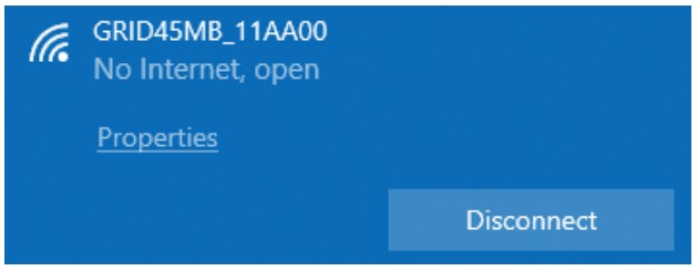 Access Web configuration by opening a web browser and navigate to the IP address 192.168.4.1. Continue to the GRID485 Web Configuration section below.
GRID485 WEB CONFIGURATION
Web Manager Entry
After navigating the browser to the GRID485’s web interface you should have the following prompt: 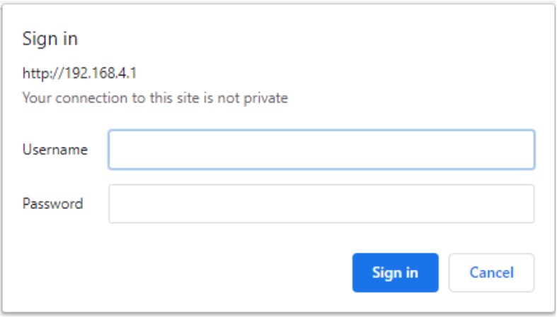
By default you should leave the User Name and the Password blank. Click “Sign in” to access the Web configuration pages.
If other Username and Password configuration settings have already been saved to the module then you should enter those security parameters instead.
Upon entering the correct Username and Password, you will see the Device Dashboard.
Device Dashboard 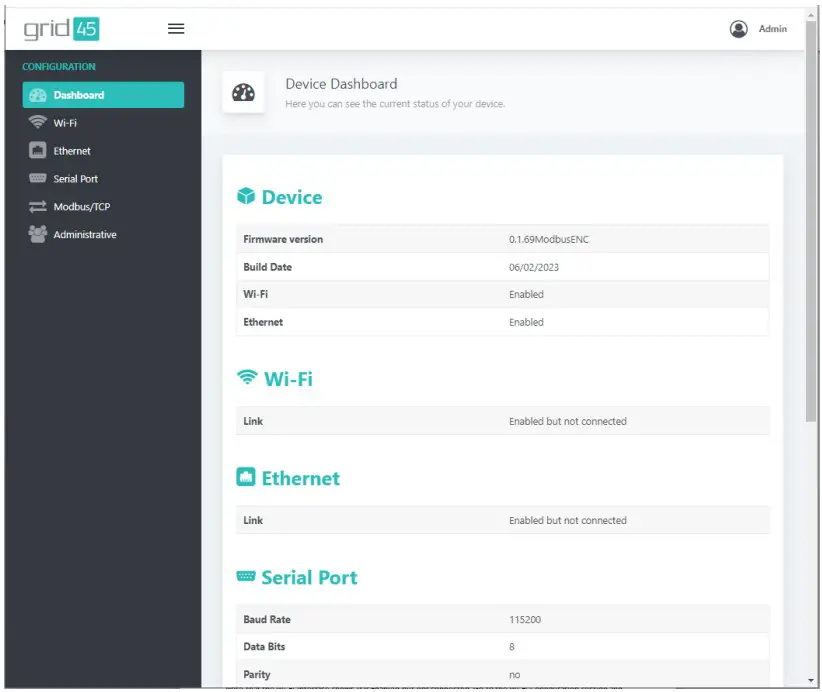
Note that the Wi-Fi Interface shows it is Enabled but not connected. Go to the Wi-Fi Configuration section and follow the steps to configure this interface. If you do not intend to use the Wi-Fi interface of the GRID485 then you should disable the Wi-Fi interface.
Go to the Ethernet Configuration section and follow the steps to configure the Ethernet interface.
Go to the Serial Port Configuration and adjust the settings to match your serial device.
Go to the Protocol Configuration and verify the settings are appropriate for your application. Refer to the user guide for your exact GRID485 firmware type and protocol for further instructions.
At this point, the GRID485 is configured and accessible on the network.
Wi-Fi Configuration
To communicate with the GRID485 device on your local Wi-fi network you will need to configure the wireless network interface. If you do not intend to use the Wi-Fi interface of the GRID485 then you should set the State to Disable Wi-Fi.
Select and click on the Wi-Fi menu option (left side).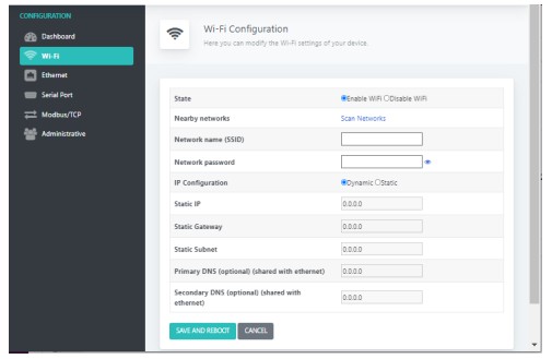
Click on Scan Networks. This displays a scan of the wireless networks within range of the device (2.4GHz band only). The available networks sorted by signal strength are shown.
Click on the matching network name (SSID) for your Wi-Fi. In the following example, “GC_Guest” has been selected. You may also enter the Network name (SSID) directly.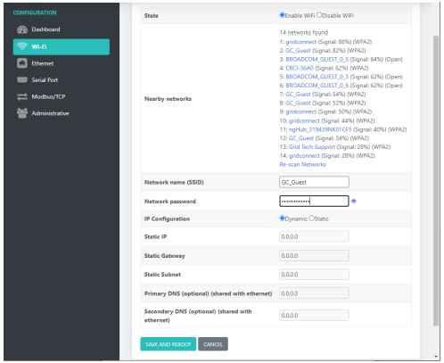
Enter the Network password (passphrase). Choose the type of IP Configuration, Dynamic (DHCP) or Static IP address. If Static, then enter the IP settings. Click the SAVE AND REBOOT button when finished.
The device will reboot and startup with the new configuration. State: Enable or Disable the Wi-Fi interface. If disabled, then the SoftAP will also be disabled. The SoftAP can be disabled separately on the Administrative settings page.
Network Name (SSID): Give the name of your Wi-Fi network.
Network password: Give the password or passphrase of your Wi-Fi network.
IP Configuration: The device will use Dynamic network settings from a local DHCP server or Static network settings assigned manually. Choose the Static option and the following settings will be made changeable.
Static IP: Sets the IP address of the device on the network (required). Make sure the IP address is unique on the network and outside the range that may be assigned by a DHCP server.
Static Gateway: Sets the IP address of the gateway on the local network. The gateway IP address only needs to be set if the device will communicate outside the local subnet.
Static Subnet: Sets the subnet mask that determines the size of the local subnet (required). Example: 255.0.0.0 for Class A, 255.255.0.0 for Class B, and 255.255.255.0 for Class C.
Primary DNS: Sets the IP address of the DNS server used as primary. The DNS setting is normally optional. Check the manual for the specific firmware type in your GRID485.
Secondary DNS: Sets the IP address of the DNS server used as secondary.
If the connection was successful, the Dashboard will show the Wi-Fi Link status as Connected.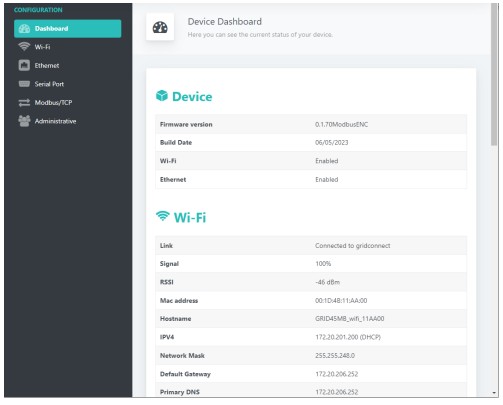
Note the IP address assigned to the module’s Wi-Fi interface.
Note the MAC address used for the Wi-FI interface is the module’s base MAC address.
Ethernet Configuration
By default the Ethernet interface will use DHCP to dynamically obtain an IP address and other network parameters. You will need to configure the Ethernet interface if you require static network parameters or if there is no DHCP server on the network.
Select and click on the Ethernet menu option (left side).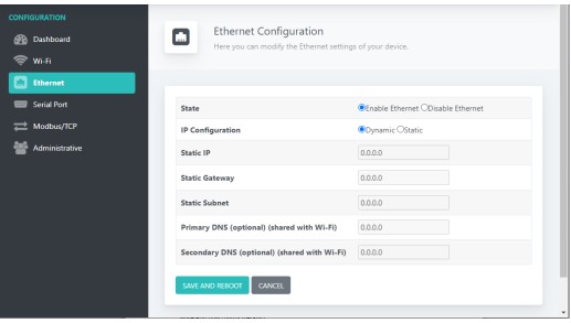
Change the IP Configuration option to Static. Be sure to set the Static IP to an available address on your network. You will need to set the Static Subnet and if the module communicates outside the local subnet you will need to set the Static Gateway IP address. The DNS settings are not used for Modbus/TCP.
Click SAVE AND REBOOT to save settings permanently.
State: Enable or Disable the wired Ethernet interface
IP Configuration: The device will use Dynamic network settings from a local DHCP server or Static network settings assigned manually. Choose the Static option and the following settings will be made changeable.
Static IP: Sets the IP address of the device on the network. Make sure the IP address is unique on the network and outside the range that may be assigned by a DHCP server.
Static Gateway: Sets the IP address of the gateway on the local network. The gateway IP address only needs to be set if the device will communicate outside the local subnet.
Static Subnet: Sets the subnet mask that determines the size of the local subnet (required). Example: 255.0.0.0 for Class A, 255.255.0.0 for Class B, and 255.255.255.0 for Class C.
Primary DNS: Sets the IP address of the DNS server used as primary. The DNS setting is normally optional. Check the manual for the specific firmware type in your GRID485.
Secondary DNS: Sets the IP address of the DNS server used as secondary.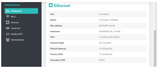 Note the MAC address used for the Ethernet interface and displayed in the Dashboard is the module’s base MAC address + 3.
Serial Port Configuration
The serial port can be configured for different baud rates, data bits, parity, stop bits and flow control. To make the serial port settings you should do the following.
Select and click on the Serial Port menu option (left side). 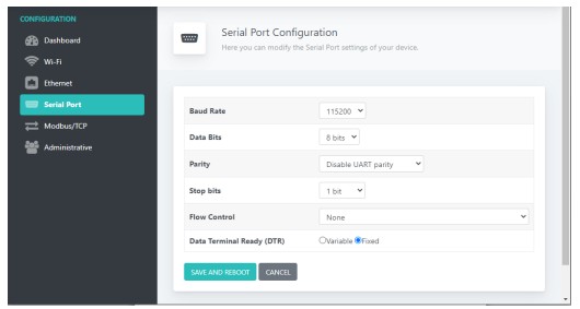
Match the configuration parameters to your serial device. Click SAVE AND REBOOT to save settings permanently.
Baud Rate: standard serial baud rates from 300 – 921600 are selectable
Data Bits: settings of 5 – 8 data bits are available. Virtually all serial protocols will require 7 or 8 data bits.
Parity: choose between Disable, Even and Odd parity.
Stop Bits: choose between 1, 1.5 and 2 stop bits
Flow Control: choose from the following options…
RS485 control, Half-duplex – for RS485 2-wire half-duplex
RS485 control, Full-duplex – for RS485 4-wire full-duplex
Administrative Configuration
The GRID485 module has an Administrative page for setting service options and updating firmware as well as factory reset, saving and restoring configuration settings.
Select and click on the Administrative menu option (left side).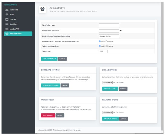
Web/telnet user: sets the user name for configuration access via web manager and telnet.
Web/telnet password: sets the password for configuration access via web manager and telnet. It also sets the
Wi-Fi passphrase for the Soft AP interface. The password must be a minimum of 8 characters.
Device Name/Location/Description: allows setting of a 22 character string to describe the device’s name,
location, function or other. This string is displayed by the Grid Connect Device manager software.
Generate WiFi network for configuration (AP): enable or disable the module’s Soft AP interface. The Soft AP interface on the module enables a Wi-Fi client on a mobile device or PC to connect one-on-one with the module.
Telnet configuration: enable or disable the module’s Telnet configuration.
Telnet port: set the TCP port number for Telnet configuration (default = 9999).
Click SAVE AND REBOOT to save settings permanently.
Download Settings
Click the DOWNLOAD SETTINGS button to download a file containing the module’s current settings for backup or for loading on other modules for duplicating the settings. The downloaded file is in JSON format and named GRID45Settings.json. The file can be renamed after download.
Note: Be careful not to duplicate the IP address on multiple modules on the network.
Upload Settings
This is used to restore configuration from a previous download. Click the Choose File button and navigate to the stored configuration file and Open. Then click the UPLOAD SETTINGS button to upload the file. The module will store the configuration and reset.
Note: The module may initialize with a new IP address stored in the configuration file.
Factory Reset
Click the FACTORY RESET button to restore the module configuration to factory defaults and the module will reset.
Note: The module may initialize with a new IP address.
The configuration can also be reset to factory defaults in hardware by pulling the Factory Reset pin high at power-on/reset for at least 1 second and then releasing the pullup, allowing the firmware to reset the configuration and initialize. The Factory Reset pin should by default have a weak pull-down to GND using a 10K ohm resistor for example.
Note: the Factory Reset pin (input) is -/GPIO39.
Firmware update
This is used to update the module’s firmware. Click the Choose File button and navigate to the stored firmware file and Open. Take care when choosing new firmware and only load firmware suitable for the module and recommended by Grid Connect technical support. Then click the FIRMWARE UPDATE button to upload the file and wait. The module will upload and store the new firmware. The upload may take around 30 seconds and may not display a progress indicator. After a successful upload the module will display a success screen and reset.
OPERATION
Asynchronous Serial
The GRID485 device supports asynchronous serial communication. This serial communication does not require a transmitted clock signal (asynchronous). Data is transmitted one byte or character at a time. Each transmitted byte consists of a start bit, 5 to 8 data bits, optional parity bit and 1 to 2 stop bits. Each bit is transmitted at the configured baud rate or data rate (eg 9600 baud). The data rate determines the length of time each bit value is maintained on the line which is referred to as the bit time. The transmitter and receiver(s) must be configured with identical settings for successful data transfer to occur.
The serial line starts in the idle state. The start bit changes the serial line to the active state for one bit time and provides the synchronization point for the receiver. The data bits follow the start bit. A parity bit can be added which is set to even or odd. The parity bit is added by the transmitter to make the number of data 1 bits an even or odd number. The parity bit is checked by the receiver to help validate the data bits were received accurately. The stop bit(s) return the serial line to an idle state for a guaranteed number of bit times before the next byte is started.
RS485
RS485 is a physical interface standard for point-to-point and point-to-multipoint serial communication. RS485 was designed to provide data communications over longer distances, higher baud rates and provide better immunity to external electro-magnetic noise. It is a differential signal with voltage levels of 0 – 5 volts. This offers superior performance by canceling the effects of ground shifts and induced noise signals that can appear as common mode voltages on a transmission line. RS485 is normally transmitted over twisted pair wiring and supports long distance serial communication (up to 4000 ft).
There is no standard RS485 connector and screw terminal connections are normally used. RS485 connections are labeled (-) and (+) or labeled A and B. RS485 communication can be done half-duplex, alternating transmitter, over a single twisted pair. For full-duplex communication two separate twisted pairs are required. In some long distance wiring applications a signal ground wire is also required. RS485 pairs may also need termination on each end of long distance wiring runs.
RS422 and RS485 use differential data transmission (balanced differential signal). This offers superior performance by canceling the effects of ground shifts and induced noise signals that can appear as common mode voltages on a network. This also allows for data transmission at much higher data rates (up to 460K bits / second) and longer distances (up to 4000 ft).
RS485 is used in applications where multiple devices want to share data communications on a single 2-wire transmission line. RS485 can support up to 32 drivers and 32 receivers on a single two wire (one twisted pair) bus. Most RS485 systems use a Client/Server architecture, where each server unit has a unique address and responds only to packets addressed to it. However, peer to peer networks are also possible.
RS422
While RS232 is well-known for connecting PC’s to external devices, RS422 and RS485 are not as well known. When communicating at high data rates, or over long distances in real world environments, single-ended methods are often inadequate. RS422 and RS485 were designed to provide data communications over longer distances, higher Baud rates and provide better immunity to external electro-magnetic noise.
What is the difference between RS422 and RS485? Like RS232, RS422 is intended for point-to-point communications. In a typical application, RS422 uses four wires (two separate Twisted Pairs of wires) to transfer data in both directions simultaneously (Full Duplex) or independently (Half Duplex). EIA/TIA-422 specifies the use of one, unidirectional driver (transmitter) with a maximum of 10 receivers. RS422 is often used in noisy industrial environments or to extend a RS232 line.
| Specification | RS-422 | RS-485 |
| Transmission Type | Differential | Differential |
| Maximum Data Rate | 10 MB/s | 10 MB/s |
| Maximum Cable Length | 4000 ft. | 4000 ft. |
| Driver Load Impedance | 100 Ohm | 54 Ohm |
| Receiver Input Resistance | 4 KOhm min | 12 KOhm min |
| Receiver Input Voltage Range | -7V to +7V | -7V to +12V |
| No of Drivers Per Line | 1 | 32 |
| No of Receivers Per Line | 10 | 32 |
![]()
Documents / Resources
 |
Grid Connect GRID485-MB Modbus TCP to Modbus RTU [pdf] User Guide GRID485-MB, GRID485-MB Modbus TCP to Modbus RTU, GRID485-MB, Modbus TCP to Modbus RTU, TCP to Modbus RTU, Modbus RTU, RTU |