Unitronics US5-B5-B1 Powerful Programmable Logic Controller

Product Information
Specifications
- Available Versions: UniStream Built-in and UniStream Built-in Pro
- Model Numbers: US5, US7, US10, US15 with various configurations
- Power Features: VNC, Multi-level password protection, Built-in alarms
- I/O Options: Various COM protocols, Fieldbus support, Advanced communication options
- Programming Software: All-in-One software for configuration and applications
Product Usage Instructions
- Before You Begin
Before installing the device, make sure to read and understand the user manual and verify the kit’s contents. - Alert Symbols and General Restrictions
Pay attention to the alert symbols for potential dangers or restrictions. Follow safety guidelines and dispose of the product properly. - Environmental Considerations
- Ensure proper ventilation with a 10mm space between device edges and enclosure walls.
- Avoid installation in areas with excessive dust, moisture, heat, or vibration.
- Avoid contact with water or high-voltage cables.
- Do not connect/disconnect the device when power is on.
Frequently Asked Questions
Q: Can I use the device without reading the user manual?
A: It is highly recommended to read and understand the user manual before using the device to ensure proper installation and operation.
Q: What should I do if I encounter a warning symbol during use?
A: If you encounter any warning symbols, refer to the associated information in the manual carefully to prevent any potential dangers or damages.
Q: Can I install the device in any environment?
A: No, follow the environmental considerations provided in the manual to ensure optimal performance and safety of the device.
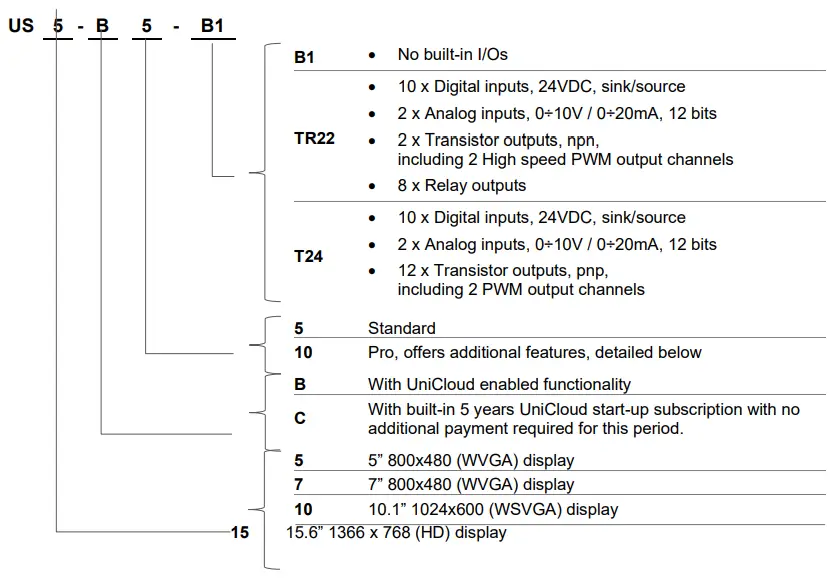
Models
- US5-B5-B1, US5-B10-B1, US5-B5-TR22, US5-B10-TR22, US5-B5-T24, US5-B10-T24, US5-C5-B1, US5-C10-B1, US5-C5-TR22, US5-C10-TR22, US5-C5-T24, US5-C10-T24
- US7-B5-B1, US7-B10-B1, US7-B5-TR22, US7-B10-TR22, US7-B5-T24, US7-B10-T24, US7-C5-B1, US7-C10-B1, US7-C5-TR22, US7-C10-TR22, US7-C5-T24, US7-C10-T24
- US10-B5-B1, US10-B10-B1, US10-B5-TR22, US10-B10-TR22, US10-B5-T24, US10-B10-T24, US10-C5-B1, US10-C10-B1, US10-C5-TR22, US10-C10-TR22, US10-C5-T24, US10-C10-T24
- US15-B10-B1, US15-C10-B1
This guide provides basic installation information for specific UniStream® models with built-in I/O. Technical specifications may be downloaded from the Unitronics website.
General Features
- Unitronics’ UniStream® Built-in series are PLC+HMI All-in-One programmable controllers that comprise a built-in CPU, an HMI panel, and built-in I/Os.
- The series is available in two versions: UniStream Built-in and UniStream Built-in Pro.
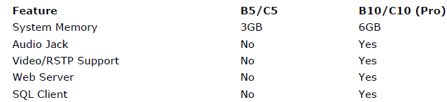
Note that a model number that includes:
- B5/C5 refers to UniStream Built-in
- B10/C10 refers to UniStream Built-in Pro. These models offer additional features, detailed below.
- HMI
- Resistive Color Touch-screens
- Rich graphic library for HMI design
- Power Features
- Built-in Trends and Gauges, auto-tuned PID, data tables, data sampling, and Recipes
- UniApps™: Access & edit data, monitor, troubleshoot & debug and more – via HMI or remotely via VNC
- Security: Multi-level password protection
- Alarms: Built-in system, ANSI/ISA standards
- I/O Options
- Built-in I/O configuration, varies according to model
- Local I/O via UAG-CX series I/O expansion adapters and standard UniStream Uni-I/O™ modules
- Remote I/O using UniStream Remote I/O or via EX-RC1
- US15 only – Integrate I/O into your system by using UAG-BACK-IOADP, and snap onto the panel for an all-in-one configuration.
- COM Options
- Built-in ports: 1 Ethernet, 1 USB host, 1 Mini-B USB device port (USB-C in US15)
- Serial and CANbus ports may be added via UAC-CX modules
- COM Protocols
- Fieldbus: CANopen, CAN Layer2, MODBUS, EtherNetIP, and more. Implement any serial RS232/485, TCP/IP, or CANbus third-party protocols via Message Composer
- Advanced: SNMP Agent/Trap, e-mail, SMS, modems, GPRS/GSM, VNC Client, FTP Server/Client
- Programming Software
All-in-One software for hardware configuration, communications, and HMI /PLC applications, available as a free download from Unitronics.
Comparison Table
Before You Begin
Before installing the device, the user must:
- Read and understand this document.
- Verify the Kit Contents.
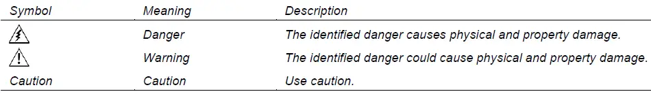
Alert Symbols and General Restrictions
When any of the following symbols appear, read the associated information carefully.
- All examples and diagrams are intended to aid understanding and do not guarantee operation. Unitronics accepts no responsibility for the actual use of this product based on these examples.
- Please dispose of this product according to local and national standards and regulations.
- This product should be installed only by qualified personnel.
- If the equipment is used in a manner not specified by the manufacturer, the protection provided by the equipment may be impaired.
- Failure to comply with appropriate safety guidelines can cause severe injury or property damage.
- Do not attempt to use this device with parameters that exceed permissible levels.
- Do not connect/disconnect the device when power is on.
Environmental Considerations
- Ventilation: 10mm space is required between the device’s top/bottom edges and the enclosure’s walls
- Do not install in areas with excessive or conductive dust, corrosive or flammable gas, moisture or rain, excessive heat, regular impact shocks, or excessive vibration, by the standards and limitations given in the product’s technical specification sheet.
- Do not place in water or let water leak onto the unit.
- Do not allow debris to fall inside the unit during installation.
- Install at maximum distance from high-voltage cables and power equipment.
UL Compliance
- The following section is relevant to Unitronics’ products that are listed with the UL.
- The following models are UL-listed for Hazardous Locations: US5-B5-B1, US5-B10-B1, US7-B5-B1 and US7-B10-B1
- The following models are UL-listed for Ordinary Locations:
- USL followed by -, followed by 050 or 070 or 101, followed by B05
- The US followed by 5 or 7 or 10, followed by -, followed by B5 or B10 or C5 or C10, followed by -, followed by B1 or TR22 or T24 or RA28 or TA30 or R38 or T42
- Models from series US5, US7, and US10 that include “T10” or “T5” in the model name are suitable for mounting on the flat surface of Type 4X enclosure. For examples: US7-T10-B1, US7-T5-R38, US5-T10-RA22 and US5-T5-T42.
UL Ordinary Location
To meet the UL ordinary location standard, panel-mount this device on the flat surface of Type 1 or 4X enclosures
UL Ratings, Programmable Controllers for Use in Hazardous Locations, Class I, Division 2, Groups A, B, C and D
These Release Notes relate to all Unitronics products that bear the UL symbols used to mark products that have been approved for use in hazardous locations, Class I, Division 2, Groups A, B, C and D.
Caution
This equipment is suitable for use in Class I, Division 2, Groups A, B, C, and D, or Non-hazardous locations only.
- Input and output wiring must be per Class I, Division 2 wiring methods and under the authority having jurisdiction.
- WARNING—Explosion Hazard—substitution of components may impair suitability for Class I, Division 2.
- WARNING – EXPLOSION HAZARD – Do not connect or disconnect equipment unless power has been switched off or the area is known to be non-hazardous.
- WARNING – Exposure to some chemicals may degrade the sealing properties of material used in Relays.
- This equipment must be installed using wiring methods as required for Class I, Division 2 as per the NEC and/or CEC.
Panel-Mounting
For programmable controllers that can be mounted also on panel, in order to meet the UL Haz Loc standard, panel-mount this device on the flat surface of Type 1 or Type 4X enclosures.
Communication and Removable Memory Storage
When products comprise either USB communication port, SD card slot, or both, neither the SD card slot nor the USB port are intended to be permanently connected, while the USB port is intended for programming only.
Removing/Replacing the battery
- When a product has been installed with a battery, do not remove or replace the battery unless the power has been switched off, or the area is known to be non-hazardous.
- Please note that it is recommended to back up all data retained in RAM, in order to avoid losing data when changing the battery while the power is switched off. Date and time information will also need to be reset after the procedure.
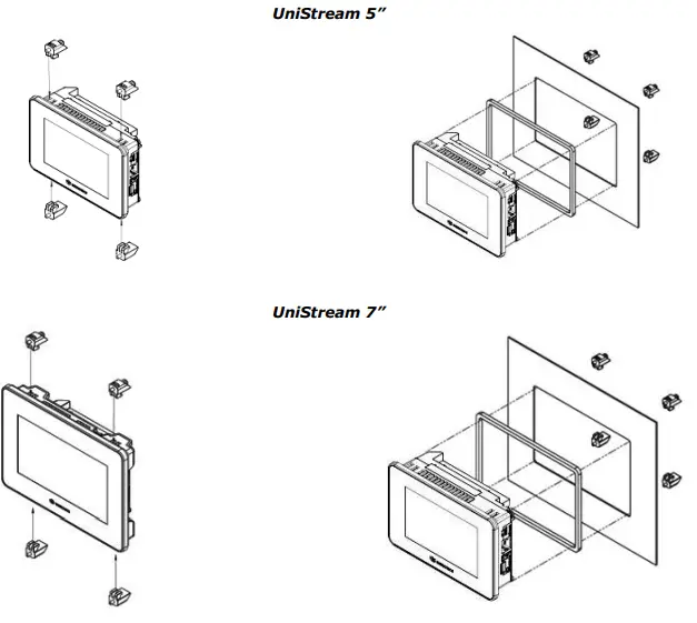
Kit Contents
- 1 PLC+HMI controller
- 4,8,10 mounting brackets (US5/US7, US10, US15)
- 1-panel mounting seal
- 2 panel supports (US7/US10/US15 only)
- 1 power terminal block
- 2 I/O terminal blocks (provided only with models comprising built-in I/Os)
- 1 Battery
Product Diagram
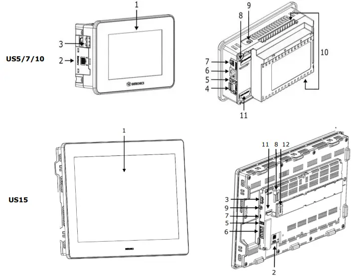
Front and Rear View
| 1 | Screen Protection | A plastic sheet is attached to the screen for protection. Remove it during the installation of the HMI Panel. |
| 2 | Battery Cover | The battery is supplied with the unit but must be installed by the user. |
| 3 | Power Supply Input | Connection point for the controller power source.
Connect the Terminal Block supplied with the kit to the end of the power cable. |
| 4 | microSD Slot | Supports standard microSD cards. |
| 5 | USB Host port | Provides the interface for external USB devices. |
| 6 | Ethernet port | Supports high-speed Ethernet communications. |
| 7 | USB Device | Use for application download and direct PC-UniStream communication. |
| 8 | I/O Expansion Jack | Connection point for an I/O Expansion Port.
Ports are supplied as part of I/O Expansion Model Kits. Kits are available by separate order. Note that UniStream® Built-in is compatible only with adapters from the series UAG-CX. |
| 9 | Audio Jack | Pro models only. This 3.5mm Audio jack enables you to connect external audio equipment. |
| 10 | Built-in I/O | Model-dependent. Present in models with built-in I/O configurations. |
| 11 | Uni-COM™ CX Module Jack | Connection point for up to 3 stack-on modules. These are available in a separate order. |
| 12 | UAG-BACK-IOADP
Adapter Jack |
Connection point for snap onto the panel for an all-in-one configuration. The adapter is available by Separate order. |
Installation Space Considerations
Allocate space for:
- the controller
- any modules that will be installed
- access to ports, jacks, and the microSD card slot
For exact dimensions, please refer to the Mechanical Dimensions shown below.
Mechanical Dimensions
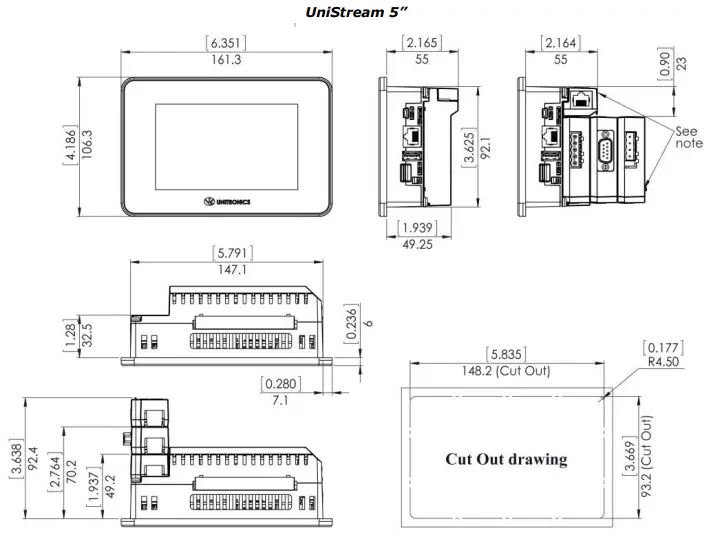
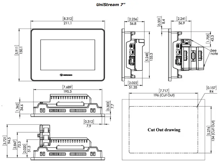
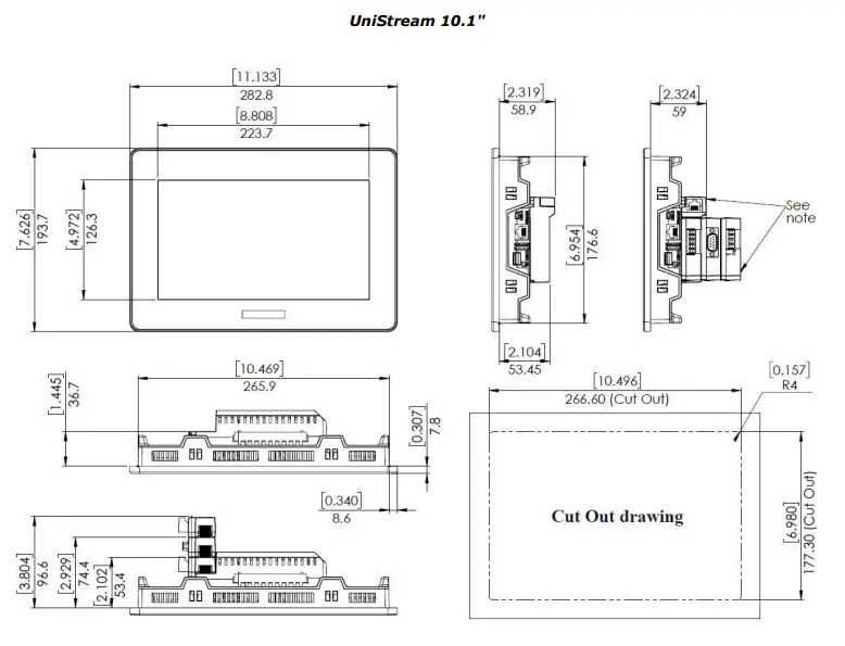
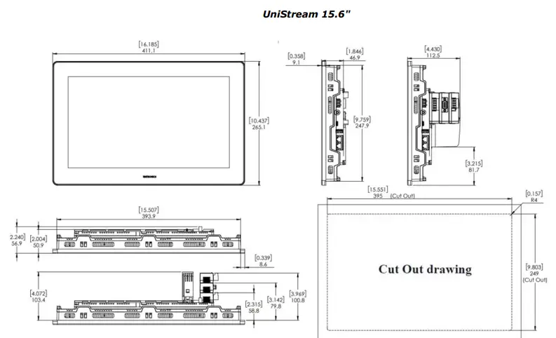
NOTE
Allow space for modules to be snapped onto the back of the controller if required by your application. Modules are available in separate order.
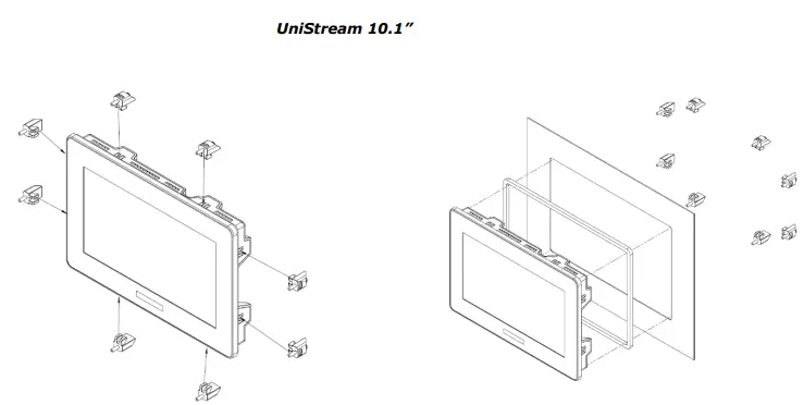
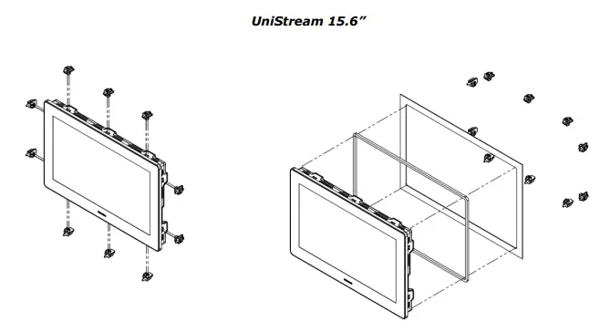
Panel Mounting
NOTE
- Mounting panel thickness must be less or equal to 5mm (0.2”).
- Ensure that the space considerations are met.
- Prepare a panel cut-out according to the dimensions as shown in the previous section.
- Slide the controller into the cut-out, ensuring that the Panel Mounting Seal is in place as shown below.
- Push the mounting brackets into their slots on the sides of the panel as shown below.
- Tighten the bracket screws against the panel. Hold the brackets securely against the unit while tightening the screws. The torque required is 0.35 N·m (3.1 in-lb).
When properly mounted, the panel is squarely situated in the panel cut-out as shown below.
Caution
Do not apply torque exceeding 0.35 N·m (3.1 in-lb) of torque to tighten the bracket screws. Using excessive force to tighten the screw can damage this product.
Battery: Back-up, First Use, Installation, and Replacement
Back-up
To preserve backup values for RTC and system data in the event of power off, the battery must be connected.
First Use
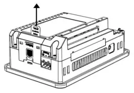
- The battery is protected by a removable cover on the side of the controller.
- The battery is supplied and installed inside the unit, with a plastic tab preventing contact which must be removed by the user.
Battery Installation and Replacement
Use proper precautions to prevent electrostatic discharge (ESD) while servicing the battery.
Caution
- To preserve backup values for RTC and system data during battery replacement, the controller must be powered.
- Note that disconnecting the battery halts the preservation of backup values and causes them to be deleted.
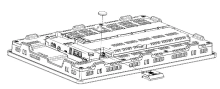
- Remove the battery cover from the controller as shown in the accompanying figure: – Press the tab on the module to disengage it. – Slide it up to remove it.
- If you are replacing the battery, remove the battery from its slot on the side of the controller.
- Insert the battery, ensuring that the polarity is aligned with the polarity marking as shown in the accompanying figure.
- Replace the battery cover.
- Dispose of the used battery according to local and national standards and regulations.

Wiring
- This equipment is designed to operate only at SELV/PELV/Class 2/Limited Power environments.
- All power supplies in the system must include double insulation. Power supply outputs must be rated as SELV/PELV/Class 2/Limited Power.
- Do not connect either the ‘Neutral’ or ‘Line’ signal of the 110/220VAC to the device’s 0V point.
- Do not touch live wires.
- All wiring activities should be performed while power is OFF.
- Use over-current protection, such as a fuse or circuit breaker, to avoid excessive currents into the power supply connection point.
- Unused points should not be connected (unless otherwise specified). Ignoring this directive may damage the device.
- Double-check all wiring before turning on the power supply.
Caution
- To avoid damaging the wire, use a maximum torque of 0.5 N·m (4.4 in-lb).
- Do not use tin, solder, or any substance on the stripped wire that might cause the wire strand to break.
- Wire and cable should have a temperature rating of a minimum of 75°C.
- Install at maximum distance from high-voltage cables and power equipment.
Wiring Procedure
Use crimp terminals for wiring; use 26-12 AWG wire (0.13 mm2 –3.31 mm2 )
- Strip the wire to a length of 7±0.5mm (0.250–0.300 inches).
- Unscrew the terminal to its widest position before inserting a wire.
- Insert the wire completely into the terminal to ensure a proper connection.
- Tighten enough to keep the wire from pulling free.
Wiring Guidelines
To ensure that the device will operate properly and to avoid electromagnetic interference:
- Use a metal cabinet. Make sure the cabinet and its doors are properly earthed.
- Use wires that are properly sized for the load.
- Use shielded twisted pair cables for wiring High Speed and Analog I/O signals. In either case, do not use the cable shield as a signal common/return path.
- Route each I/O signal with its dedicated common wire. Connect common wires at their respective common (CM) points at the controller.
- Individually connect each 0V point and each common (CM) point in the system to the power supply 0V terminal, unless otherwise specified.
- Individually connect each functional ground point (
 ) to the earth of the system (preferably to the metal cabinet chassis). Use the shortest and thickest wires possible: less than 1m (3.3’) in length, minimum thickness 14 AWG (2 mm2).
 - Connect the power supply 0V to the earth of the system.
Earthing the cables’ shield:
- Connect the cable shield to the earth of the system (preferably to the metal cabinet chassis). Note that the shield must be connected only at one end of the cable; it is recommended to earth the shield at the PLC side.
- Keep shield connections as short as possible.
- Ensure shield continuity when extending shielded cables.
NOTE
For detailed information, refer to the document System Wiring Guidelines, located in the Technical Library on the Unitronics’ website.
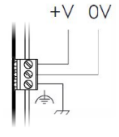
Wiring the Power Supply
The controller requires an external power supply.
- In the event of voltage fluctuations or non-conformity to voltage power supply specifications, connect the device to a regulated power supply.
Connect the +V and 0V terminals as shown in the accompanying figure.
Connecting Ports
- Ethernet
CAT-5e shielded cable with RJ45 connector - USB Device
Standard USB cable with Mini-B USB plug (USC-C plugin US15) - USB Host
Standard USB device with Type-A plug
Connecting Audio
Audio-Out
Use a 3.5mm stereo audio plug with a shielded audio cable Note that only Pro models support this feature.
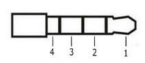
Audio Pinout
- Headphone Left Out (Tip)
- Headphone Right Out (Ring)
- Ground (Ring)
- Don’t connect (Sleeve)
Note that below, the letter “xx” that is used in the model numbers means that the section refers both to B5/C5 and B10/C10 models.
- US5 -xx-TR22, US5-xx-T24
- US7-xx-TR22, US7-xx-T24
- US10 -xx-TR22, US10-xx-T24
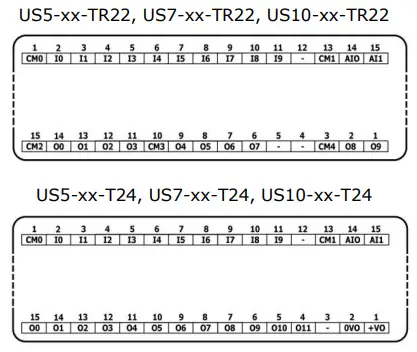
I/O Connection Points
The IOs for these models are arranged in two groups of fifteen points each, as shown in the figures to the right.
Top group
Input connection points
Bottom group
Output connection points
The function of certain I/Os may be adapted via wiring and software settings.
Wiring the Digital Inputs
All 10 digital inputs share the common point CM0. The digital inputs may be wired together as a sink or source.
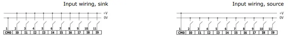
NOTE
Use sink input wiring to connect a sourcing (pnp) device. Use source input wiring to connect a sinking (npn) device.
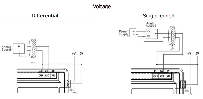
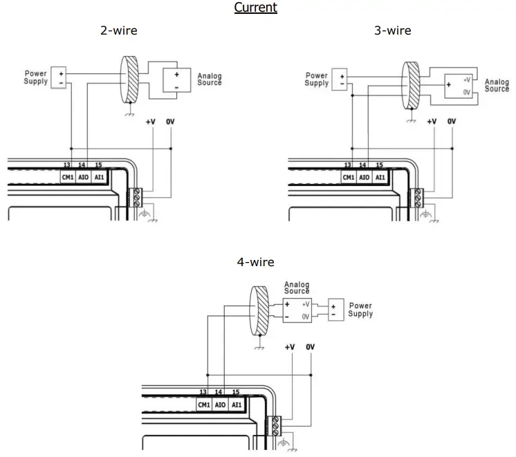
Wiring the Analog Inputs
Both inputs share the common point CM1.
NOTE
- The inputs are not isolated.
- Each input offers two modes: voltage or current. You can set each input independently.
- The mode is determined by the hardware configuration within the software application.
- Note that if, for example, you wire the input to current, you must also set it to current in the software application.
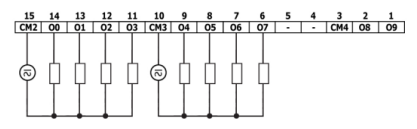
Wiring the Relay Outputs (US5-xx-TR22, US7-xx-TR22, US10-xx-TR22)
To avoid the risk of fire or property damage, always use a limited current source or connect a current limiting device in series with the relay contacts
The relay outputs are arranged in two isolated groups:
- O0-O3 share the common return CM2.
- O4-O7 shares the common return CM3.
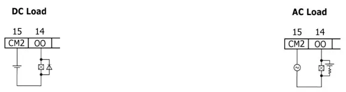
Increasing Contact Life Span
To increase the life span of the relay contacts and protect the controller from potential damage by reverse EMF, connect:
- a clamping diode in parallel with each inductive DC load,
- a RC snubber circuit in parallel with each inductive AC load
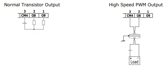
Wiring the Sink Transistor Outputs
(US5-xx-TR22, US7-xx-TR22, US10-xx-TR22)
- Connect a current limiting device in series with outputs O8 and O9. These outputs are not short-circuit protected.
- Outputs O8 and O9 can independently be configured as either normal digital outputs or as high-speed PWM outputs.
- Outputs O8 and O9 share the common point CM4.
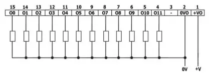
Wiring the Source Transistor Outputs
(US5-xx-T24, US7-xx-T24, US10-xx-T24)
- Output’s power supply
The use of any of the outputs requires an external 24VDC power supply as shown in the accompanying figure. - Outputs
- Connect the +VO and 0VO terminals as shown in the accompanying figure.
- O0-O11 share common return 0VO.
Installing Uni-I/O™ & Uni-COM™ Modules
Refer to the Installation Guides provided with these modules.
- Turn off system power before connecting or disconnecting any modules or devices.
- Use proper precautions to prevent electrostatic discharge (ESD).
Uninstalling the Controller
- Disconnect the power supply.
- Remove all wiring and disconnect any installed devices according to the device’s installation guide.
- Unscrew and remove the mounting brackets, taking care to support the device to prevent it from falling during this procedure.
The information in this document reflects products at the date of printing. Unitronics reserves the right, subject to all applicable laws, at any time, at its sole discretion, and without notice, to discontinue or change the features, designs, materials, and other specifications of its products, and to either permanently or temporarily withdraw any of the forgoing from the market. All information in this document is provided “as is” without warranty of any kind, either expressed or implied, including but not limited to any implied warranties of merchantability, fitness for a particular purpose, or non-infringement. Unitronics assumes no responsibility for errors or omissions in the information presented in this document. In no event shall Unitronics be liable for any special, incidental, indirect, or consequential damages of any kind, or any damages whatsoever arising out of or in connection with the use or performance of this information. The tradenames, trademarks, logos, and service marks presented in this document, including their design, are the property of Unitronics (1989) (R”G) Ltd. or other third parties and you are not permitted to use them without the prior written consent of Unitronics or such third party as may own them.
Technical Specifications
- US5-B5-B1, US5-B10-B1, US5-B5-TR22, US5-B10-TR22, US5-B5-T24, US5-B10-T24, US5-C5-B1, US5-C10-B1, US5-C5-TR22, US5-C10-TR22, US5-C5-T24, US5-C10-T24
- US7-B5-B1, US7-B10-B1, US7-B5-TR22, US7-B10-TR22, US7-B5-T24, US7-B10-T24, US7-C5-B1, US7-C10-B1, US7-C5-TR22, US7-C10-TR22, US7-C5-T24, US7-C10-T24
- US10-B5-B1, US10-B10-B1, US10-B5-TR22, US10-B10-TR22, US10-B5-T24, US10-B10-T24, US10-C5-B1, US10-C10-B1, US10-C5-TR22, US10-C10-TR22, US10-C5-T24, US10-C10-T24
- US15-B10-B1, US15-C10-B1
Unitronics’ UniStream® Built-in series are PLC+HMI All-in-One programmable controllers that comprise built-in HMI and built-in I/Os. UniStream connects directly to UniCloud, Unitronics’ IIoT cloud platform using built-in UniCloud connectivity. More information about UniCloud is available at www.unitronics.cloud.
Model numbers in this document
Installation Guides are available in the Unitronics Technical Library at www.unitronicsplc.com.
| Power Supply | USx-xx-B1 | USx-xx-TR22 | USx-xx-T24 | |
| Input voltage | 12VDC or 24VDC | 24VDC | 24VDC | |
| Permissible range | 10.2VDC to 28.8VDC | 20.4VDC to 28.8VDC | 20.4VDC to 28.8VDC | |
| Max. current
consumption |
US5 | 0.7A@12VDC
0.4A@24VDC |
0.44A@24VDC | 0.4A@24VDC |
| US7 | 0.79A@12VDC
0.49A@24VDC |
0.53A@24VDC | 0.49A@24VDC | |
| US10 | 0.85A@12VDC
0.52A@24VDC |
0.56A@24VDC | 0.52A@24VDC | |
| US15 | 2.2A@12VDC
1.1A@24VDC |
None | None | |
| Isolation | None | |||
| Display | UniStream 5″ | UniStream 7″ | UniStream 10.1″ | UniStream 15.6″ |
| LCD type | TFT | |||
| Backlight type | White LED | |||
| Luminous intensity (brightness) | Typically 350 nits (cd/m2), at 25°C | Typically 400 nits (cd/m2), at 25°C | Typically 300 nits (cd/m2), at 25°C | Typically 400 nits (cd/m2), at 25°C |
| Backlight longevity
(1) |
30k hours | |||
| Resolution (pixels) | 800 x 480 (WVGA) | 1024 x 600 (WSVGA) | 1366 x 768 (HD) | |
| Size | 5” | 7″ | 10.1″ | 15.6” |
| Viewing area | Width x Height (mm) 108 x 64.8 | Width x Height (mm)
154.08 x 85.92 |
Width x Height (mm) 222.72 x 125.28 | Width x Height (mm) 344.23 x 193.53 |
| Color support | 65,536 (16bit) | |||
| Surface treatment | Anti-glare | |||
| Touch screen | Resistive Analog | |||
| Actuation force (min) | > 80 g (0.176 lb) | |||
| General | |
| I/O support | Up to 2,048 I/O points |
| Built-in I/O | According to model |
| Local I/O expansion | To add local I/Os, use UAG-CX I/O Expansion Adapters (2). These adapters provide the connection point for standard UniStream Uni-I/O™ modules.
You can connect up to 80 I/O modules to a single controller using these adapters. US15 only – Integrate I/O into your system by using the UAG-BACK-IOADP adapter, and snap onto the panel for an all-in-one configuration. |
| Remote I/O | Up to 8 UniStream Remote I/O Adapters (URB) |
| Communication ports | |
| Built-in COM ports | Specifications are provided below in the section Communications |
| Add-on Ports | Add up to 3 ports to a single controller using Uni-COM™ UAC-CX Modules (3). |
| Internal memory | Standard (B5/C5) | Pro (B10/C10) |
| RAM: 512MB
ROM: 3GB system memory 1GB user memory |
RAM: 1GB
ROM: 6GB system memory 2GB user memory |
|
| Ladder memory | 1 MB | |
| External memory | microSD or microSDHC card
Size: up to 32GB, Data Speed: up to 200Mbps |
| Bit operation | 0.13 µs |
| Battery | Model: 3V CR2032 Lithium battery (4)
Battery lifetime: 4 years typical, at 25°C Battery Low detection and indication (via the HMI and System Tag). |
| Audio (Pro B10/C10 models only) | |
| Bit Rate | 192kbps |
| Audio compatibility | Stereo MP3 files |
| Interface | 3.5mm Audio-out jack – use shielded audio cable of up to 3 m (9.84 ft) |
| Impedance | 16Ω, 32Ω |
| Isolation | None |
| Video (Pro B10/C10 models only) | |
| Supported Formats | MPEG-4 Visual , AVC/H.264 |
| Communication (Built-in Ports) | US5, US7, US10 | US15 |
| Ethernet port | ||
| Number of ports | 1 | 2 |
| Port type | 10/100 Base-T (RJ45) | |
| Auto crossover | Yes | |
| Auto-negotiation | Yes | |
| Isolation voltage | 500VAC for 1 minute | |
| Cable | Shielded CAT5e cable, up to 100 m (328 ft) | |
| USB device | ||
| Port type | Mini-B | USB-C |
| Data rate | USB 2.0 (480Mbps) | |
| Isolation | None | |
| Cable | USB 2.0 compliant; < 3 m (9.84 ft) | |
| USB host | ||
| Over current protection | Yes | |
| Digital Inputs (T24,TR22 models) | |
| Number of inputs | 10 |
| Type | Sink or Source |
| Isolation voltage | |
| Input to bus | 500VAC for 1 minute |
| Input to input | None |
| Nominal voltage | 24VDC @ 6mA |
| Input voltage | |
| Sink/Source | On state: 15-30VDC, 4mA min. Off state: 0-5VDC, 1mA max. |
| Nominal impedance | 4kΩ |
| Filter | 6ms typical |
| Analog Inputs (T24,TR22 models) | |||
| Number of inputs | 2 | ||
| Input range (6) (7) | Input Type | Nominal Values | Over-range Values * |
| 0 ÷ 10VDC | 0 ≤ Vin ≤ 10VDC | 10 < Vin ≤ 10.15VDC | |
| 0 ÷ 20mA | 0 ≤ Iin ≤ 20mA | 20 < Iin ≤ 20.3mA | |||||
| * Overflow (8) is declared when an input value exceeds the Over-range boundary. | |||||||
| Absolute maximum rating | ±30V (Voltage), ±30mA (Current) | ||||||
| Isolation | None | ||||||
| Conversion method | Successive approximation | ||||||
| Resolution | 12 bits | ||||||
| Accuracy
(25°C / -20°C to 55°C) |
±0.3% / ±0.9% of full scale | ||||||
| Input impedance | 541kΩ (Voltage), 248Ω (Current) | ||||||
| Noise rejection | 10Hz, 50Hz, 60Hz, 400Hz | ||||||
| Step response (9)
(0 to 100% of final value) |
Smoothing | Noise Rejection Frequency | |||||
| 400Hz | 60Hz | 50Hz | 10Hz | ||||
| None | 2.7ms | 16.86ms | 20.2ms | 100.2ms | |||
| Weak | 10.2ms | 66.86ms | 80.2ms | 400.2ms | |||
| Medium | 20.2ms | 133.53ms | 160.2ms | 800.2ms | |||
| Strong | 40.2ms | 266.86ms | 320.2ms | 1600.2ms | |||
| Update time (9) | Noise Rejection Frequency | Update Time |
| 400Hz | 5ms | |
| 60Hz | 4.17ms | |
| 50Hz | 5ms | |
| 10Hz | 10ms | |
| Operational signal range (signal + common mode) | Voltage mode – AIx: -1V ÷ 10.5V ; CM1: -1V ÷ 0.5V Current mode – AIx: -1V ÷ 5.5V ; CM1: -1V ÷ 0.5V
(x=0 or 1) |
|
| Cable | Shielded twisted pair | |
| Diagnostics (8) | Analog input overflow | |
| Relay Outputs (USx-xx-TR22) | |
| Number of outputs | 8 (O0 to O7) |
| Output type | Relay, SPST-NO (Form A) |
| Isolation groups | Two groups of 4 outputs each |
| Isolation voltage | |
| Group to bus | 1,500VAC for 1 minute |
| Group to group | 1,500VAC for 1 minute |
| Output to output within the group | None |
| Current | 2A maximum per output (Resistive load) |
| Voltage | 250VAC / 30VDC maximum |
| Minimum load | 1mA, 5VDC |
| Switching time | 10ms maximum |
| Short-circuit protection | None |
| Life expectancy (10) | 100k operations at maximum load |
| Sink Transistor Outputs (USx-xx-TR22) | |
| Number of outputs | 2 (O8 and O9) |
| Output type | Transistor, Sink |
| Isolation | |
| Output to bus | 1,500VAC for 1 minute |
| Output to output | None |
| Current | 50mA max. per output |
| Voltage | Nominal: 24VDC
Range: 3.5V to 28.8VDC |
| On-state voltage drop | 1V max |
| Off-state leakage current | 10µA max |
| Switching times | Turn-on: 1.6ms max. )4kΩ load, 24V) Turn-off: 13.4ms max. )4kΩ load, 24V) |
| High-speed outputs | |
| PWM Frequency | 0.3Hz min.
30kHz max. )4kΩ load( |
| Cable | Shielded twisted pair |
| Source Transistor Outputs (USx-xx-T24) | |
| Number of outputs | 12 |
| Output type | Transistor, Source (pnp) |
| Isolation voltage | |
| Output to bus | 500VAC for 1 minute |
| Output to output | None |
| Outputs power supply to bus | 500VAC for 1 minute |
| Outputs power supply to output | None |
| Current | 0.5A maximum per output |
| Voltage | See the Source Transistor Outputs Power Supply specification below |
| ON state voltage drop | 0.5V maximum |
| OFF-state leakage current | 10µA maximum |
| Switching times | Turn-on: 80ms maximum, Turn-off: 155ms maximum (Load resistance < 4kΩ( |
| PWM Frequency (11) | O0, O1:
3kHz max. (Load resistance < 4kΩ) |
| Short-circuit protection | Yes |
| Source Transistor Outputs Power Supply (USx-xx-T24) | |
| Nominal operating voltage | 24VDC |
| Operating voltage | 20.4 – 28.8VDC |
| Maximum current consumption | 30mA@24VDC
Current consumption does not include load current |
| Environmental | US5, US7, US10 | US15 |
| Protection | Front face: IP66, NEMA 4X Rear side: IP20, NEMA1 | |
| Operating temperature | -20°C to 55°C (-4°F to 131°F) | 0°C to 50°C (32°F to 122°F) |
| Storage temperature | -30°C to 70°C (-22°F to 158°F) | -20°C to 60°C (-4°F to 140°F) |
| Relative Humidity (RH) | 5% to 95% (non-condensing) | |
| Operating Altitude | 2,000 m (6,562 ft) | |
| Shock | IEC 60068-2-27, 15G, 11ms duration | |
| Vibration | IEC 60068-2-6, 5Hz to 8.4Hz, 3.5mm constant amplitude, 8.4Hz to 150Hz, 1G acceleration | |
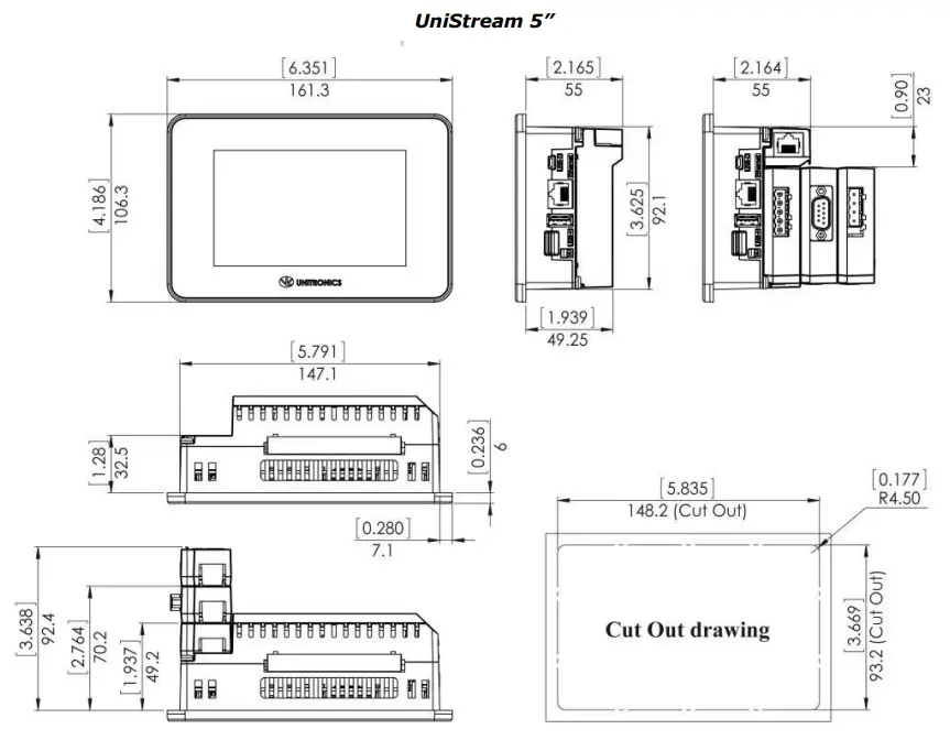
| Dimensions | ||
| Weight | Size | |
| US5-xx-B1 | 0.31 Kg (0.68 lb) | Refer to the images
UniStream 5” UniStream 7” UniStream 10.1” |
| US5-xx-TR22 | 0.37 Kg (0.81 lb) | |
| US5-xx-T24 | 0.35 Kg (0.77 lb) | |
| US7-xx-B1 | 0.62 Kg (1.36 lb) | Refer to the images
UniStream 15.6” |
| US7-xx-TR22 | 0.68 Kg (1.5 lb) | |
| US7-xx-T24 | 0.68 Kg (1.5 lb) | |
| US10-xx-B1 | 1.02 Kg (2.25 lb) | Refer to the images
UniStream 15.6” |
| US10-xx-TR22 | 1.08 Kg (2.38 lb) | |
| US10-xx-T24 | 1.08 Kg (2.38 lb) | |
| US15-xx-B1 | 2.68Kg (5.9 lb) |
Important Notes
- The HMI panel’s backlight longevity is the typical operating time after which the brightness drops to 50% of its original level.
- UAG-CX Expansion Adapter Kits comprise a Base unit, an End unit, and a connecting cable. You plug the Base Unit into the controller’s I/O Expansion Jack and connect standard UniStream Uni-I/O™ modules. For more information, refer to the product’s installation guide and technical specifications.
- Uni-COM™ CX modules plug directly into the Uni-COM™ CX Module Jack on the back of the controller. UAC-CX modules may be installed in the following configurations: – If a module comprising a serial port is snapped directly into the back of UniStream, it may be followed only by another serial module, for a total of 2. – If your configuration includes a CANbus module, it must be snapped directly to the back of UniStream. The CANbus module may be followed by up to two serial modules, for a total of 3. For more information, refer to the product’s installation guide and technical specifications.
- When replacing the unit’s battery, make sure that the new one has environmental specifications that are similar to or better than the one specified in this document.
- The USB device port is used to connect the device to a PC.
- The 4-20mA input option is implemented using the 0-20mA input range.
- The analog inputs measure values that are slightly higher than the nominal input range (Input Over-range).
Note that when the input overflow occurs, it is indicated in the corresponding I/O Status tag while the input value is registered as the maximum permissible value. For example, if the specified input range is 0 ÷ 10V, the Over-range values can reach up to 10.15V, and any input voltage higher than that will still register as 10.15V while the Overflow system tag is turned on. - The diagnostics results are indicated in the system tags and can be observed through the UniApps™ or the online state of the UniLogic™.
- Step response and update time are independent of the number of channels that are used.
- The life expectancy of the relay contacts depends on the application that they are used in. The product’s installation guide provides procedures for using the contacts with long cables or with inductive loads.
- Outputs O0 and O1 can be configured as either normal digital outputs or as PWM outputs. PWM output specifications apply only when outputs are configured as PWM outputs.
The information in this document reflects products at the date of printing. Unitronics reserves the right, subject to all applicable laws, at any time, at its sole discretion, and without notice, to discontinue or change the features, designs, materials, and other specifications of its products, and to either permanently or temporarily withdraw any of the forgoing from the market. All information in this document is provided “as is” without warranty of any kind, either expressed or implied, including but not limited to any implied warranties of merchantability, fitness for a particular purpose, or non-infringement. Unitronics assumes no responsibility for errors or omissions in the information presented in this document. In no event shall Unitronics be liable for any special, incidental, indirect, or consequential damages of any kind, or any damages whatsoever arising out of or in connection with the use or performance of this information. The tradenames, trademarks, logos, and service marks presented in this document, including their design, are the property of Unitronics (1989) (R”G) Ltd. or other third parties and you are not permitted to use them without the prior written consent of Unitronics or such third party as may own them.
Documents / Resources
 |
Unitronics US5-B5-B1 Powerful Programmable Logic Controller [pdf] User Guide US5-B5-B1, US5-B10-B1, US5-B5-TR22, US5-B10-TR22, US5-B5-T24, US5-B10-T24, US5-C5-B1, US5-C10-B1, US5-C5-TR22, US5-C10-TR22, US5-C5-T24, US5-C10-T24, US7-B5-B1, US7-B10-B1, US7-B5-TR22, US7-B10-TR22, US7-B5-T24, US7-B10-T24, US7-C5-B1, US7-C10-B1, US7-C5-TR22, US7-C10-TR22, US7-C5-T24, US7-C10-T24, US10-B5-B1, US10, US5-B5-B1 Powerful Programmable Logic Controller, US5-B5-B1, Powerful Programmable Logic Controller, Programmable Logic Controller, Logic Controller, Controller |


