![]()
V2403C Series
Quick Installation Guide
Embedded Computers
Version 1.1, February 2022
Technical Support Contact Information
www.moxa.com/support
Overview
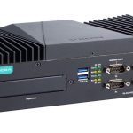
The V2403C Series embedded computers are based on the Intel® 7th generation processor and feature 4 RS-232/422/485 serial ports, 4 LAN ports, and 4 USB 3.0 ports. The V2403C computers come with 1 DisplayPort and 1 HDMI port with 4-k resolution support, fulfilling various requirements for industrial applications.
The mSATA slot, SATA connectors, and USB ports provide the V2403C computers with the reliability needed for industrial applications that require storage expansion for data buffering.
Package Checklist
Each basic system model package is shipped with the following items:
- V2403C Series embedded computer
- Wall-mounting kit
- Storage disk tray package
- HDMI cable locker
- Quick installation guide (printed)
- Warranty card
Hardware Installation
Front View

Dimensions

LED Indicators
The following table describes the LED indicators located on the front and rear panels of the V2403C computer.
| LED Name | Status | Function |
| Power
(On power button) |
Green | Power is on |
| Off | No power input or any other power error | |
| Ethernet
(100 Mbps) (1000 Mbps) |
Green | Steady On: 100 Mbps Ethernet link Blinking: Data transmission is in progress |
| Yellow | Steady On 1000 Mbps Ethernet link Blinking: Data transmission is in progress | |
| Off | Data transmission speed at 10 Mbps or the cable is not connected | |
| Serial (TX/RX) | Green | Tx: Data transmission is in progress |
| Yellow | Rx: Receiving Data | |
| Off | No operation | |
| Storage | Yellow | Data is being accessed from either the mSATA or the SATA drives |
| Off | Data is not being accessed from the storage drives |
Installing the V2403C
The V2403C computer comes with two wall-mounting brackets. Attach the brackets to the computer using four screws on each side. Ensure that the mounting brackets are attached to the V2403C computer in the direction shown in the following figure.

The eight screws for the mounting brackets are included in the product package. They are standard IMS_M3x5L screws and require a torque of 4.5 kg-cm. Refer to the following illustration for details.

Use two screws (M3*5L standard is recommended) on each side to attach the V2403C to a wall or cabinet. The product package does not include the four screws required for attaching the wall-mounting kit to the wall; they need to be purchased separately. Ensure that the V2403C computer is installed in the direction shown in the following figure.

Connecting the Power
The V2403C computers are provided with 3-pin power input connectors in a terminal block on the front panel. Connect the power cord wires to the connectors and then tighten the connectors. Push the power button.
The Power LED (on the power button) will light up to indicate that power is being supplied to the computer. It should take about 30 to 60 seconds for the operating system to complete the boot-up process.

| Pin 1 | Definition |
| 1 | V+ |
| 2 | V- |
| 3 | Ignition |
The power input specification is given below:
• The DC power source rating is 12 V @ 5.83 A, 48 V @ 1.46 A, and a minimum of 18 AWG.
For surge protection, connect the grounding connector located below the power connector with the earth (ground) or a metal surface.
In addition, there is an ignition control switch on the front panel, which can be used to control the power input. Refer to the V2403C Hardware User’s Manual for details.
Connecting Displays
The V2403C has 1 display port connector on the rear panel. In addition, another HDMI interface is also provided on the rear panel.
NOTE In order to have highly reliable video streaming, use premium HDMI-certified cables.
USB Ports
The V2403C comes with 4 USB 3.0 ports on the front panel. The USB ports can be used to connect to other peripherals, such as keyboard, mouse, or flash drives for expanding the system’s storage capacity.
Serial Ports
The V2403C comes with 4 software-selectable RS-232/422/485 serial ports on the rear panel. The ports use DB9 male connectors. Refer to the following table for pin assignments:
| Pin | RS-232 | RS-422 | RS-485 (4-wire) |
RS-485 (2-wire) |
| 1 | DCD | TDA(-) | TDA(-) | |
| 2 | RxD | TxDB(+) | TxDB(+) | |
| 3 | TxD | RxDB(+) | RxDB(+) | DataB(+) |
| 4 | DTR | RxDA(-) | RxDA(-) | DataA(-) |
| 5 | GND | GND | GND | GND |
| 6 | DSR | |||
| 7 | RTS | |||
| 8 | CTS |

Ethernet Ports
The V2403C has 4 100/1000 Mbps RJ45 Ethernet ports with RJ45 connectors on the front panel. Refer to the following table for the pin assignments:
| Pin | 10/100 Mbps | 1000 Mbps |
| 1 | ETx+ | TRD(0)+ |
| 2 | ETx- | TRD(0)- |
| 3 | ERx+ | TRD(1)+ |
| 4 | – | TRD(2)+ |
| 5 | – | TRD(2)- |
| 6 | ERx- | TRD(1)- |
| 7 | – | TRD(3)+ |
| 8 | – | TRD(3)- |
 NOTE For reliable Ethernet connections, we recommend enabling the ports in standard temperatures and keeping them enabled in high/low-temperature environments.
Digital Inputs/Digital Outputs
The V2403C comes with 4 digital inputs and 4 digital outputs in a terminal block. Refer to the following figures for the pin definitions and the current ratings.
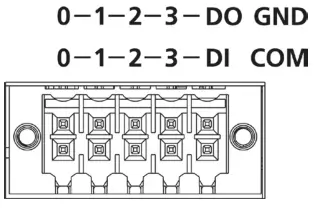
| Digital Inputs Dry Contact Logic 0: Short to Ground Logic 1: Open Wet Contact (DI to COM) Logic 1: 10 to 30 VDC Logic 0: 0 to 3 VDC |
Digital Outputs Current Rating: 200 mA per channel Voltage: 24 to 30 VDC |
For detailed wiring methods, refer to the V2403C Hardware User’s Manual.
Installing Storage Disks
The V2403C comes with two 2.5-inch storage sockets, allowing users to install two disks for data storage.
Follow these steps to install a hard disk drive.
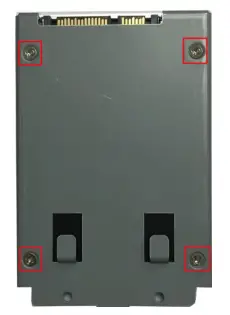
- Unpack the storage disk tray
- Place the disk drive on the tray. from the product package.

- Turn the disk and tray arrangement around to view the rear side of the tray. Fasten the four screws to secure the disk to the tray.
- Remove all screws on the rear panel of the V2403C computer.

- Take out the rear cover of the computer and find the location of the storage disk sockets. There are two sockets for the storage disk tray; you may install them on either socket.
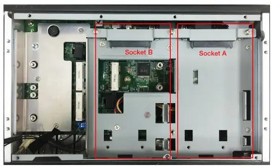
- To place the storage disk tray, put the end of the tray near the groove on the socket.
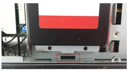
- Place the tray on the socket and push upward so that the connectors on the storage disk tray and the socket can be connected. Fasten two screws on the bottom of the tray.

For instructions on installing other peripheral devices or wireless modules, refer to the V2403C Hardware User’s Manual.
NOTE This computer is intended to be installed in a restricted access area only. In addition, for safety reasons, the computer should be installed and handled only by qualified nd experienced professionals.
NOTE This computer is designed to be supplied by listed equipment rated 12 to 48 VDC, minimum 5.83 to 1.46 A, and minimum Tma=70˚C. If you need assistance with purchasing a power adapter, contact the Moxa technical support team.
NOTE If using a Class I adapter, the power cord adapter should be connected to a socket outlet with an earthing connection or the power cord and adapter must comply with Class II construction.
Replacing the Battery
The V2403C comes with one slot for a battery, which is installed with a lithium battery with 3 V/195 mAh specifications. To replace the battery, follow the steps below:
- The battery cover is located on the rear panel of the computer.

- Unfasten the two screws on the battery cover.

- Take off the cover; the battery is attached to the cover.

- Separate the connector and remove the two screws on the metal plate.

- Replace the new battery in the battery holder, place the metal plate on the battery, and fasten the two screws tightly.

- Reconnect the connector, place the battery holder into the slot, and secure the cover of the slot by fastening the two screws on the cover
NOTE • Be sure to use the correct type of battery. The incorrect battery may cause system damage. Contact Moxa’s technical support staff for assistance, if necessary.
• To reduce the risk of fire or burns, do not disassemble, crush, or puncture the battery; do not dispose of it in fire or water, and do not short external contacts.
 ATTENTION
Before connecting the V2403C to the DC power inputs, make sure the DC power source voltage is stable.
The wiring for the input terminal block shall be installed by a skilled person.
• Wire type: Cu
• Only use 28-18 AWG wire size and a torque value of 0.5 Nm.
• Use only one conductor in a clamping point between the DC power source and the power input.
Documents / Resources
 |
MOXA V2403C Series Fanless x86 Embedded Computers for IIoT [pdf] Installation Guide V2403C Series, Fanless x86 Embedded Computers for IIoT |