LS XPL-BSSA Programmable Logic Controller
This installation guide provides simple function information for PLC control. Please read carefully this data sheet and manuals carefully before using the products. Especially read the precautions, then handle the products properly.
Safety Precautions
- Meaning of warning and caution label
WARNING
indicates a potentially hazardous situation which, if not avoided, could result in death or serious injury.
CAUTION
indicates a potentially hazardous situation which, if not avoided, may result in minor or moderate injury. It may also be used to alert against unsafe practices
WARNING
- Do not contact the terminals while the power is applied.
- Be sure there are no foreign metallic matters.
- Do not manipulate the battery(charge, disassemble, hitting, short, soldering).
CAUTION
- Be sure to check the rated voltage and terminal arrangement before wiring
- When wiring, tighten the screw of terminal block with the specified torque range
- Do not install flammable things on the surroundings
- Do not use the PLC in an environment of direct vibration
- Except for expert service staff, do not disassemble or fix or modify the product
- Use the PLC in an environment that meets the general specifications contained in this datasheet.
- Be sure that the external load does not exceed the rating of the output module.
- When disposing of the PLC and battery, treat it as industrial waste.
- I/O signal or communication line shall be wired at least 100mm away from a high-voltage cable or power line.
Operating Environment
- To install, observe the following conditions.
| No | Item | Specification | Standard | |||
| 1 | Ambient temp. | 0 ~ 55℃ | – | |||
| 2 | Storage temp. | -25 ~ 70℃ | – | |||
| 3 | Ambient humidity | 5 ~ 95%RH, non-condensing | – | |||
| 4 | Storage humidity | 5 ~ 95%RH, non-condensing | – | |||
|
5 |
Vibration Resistance |
Occasional vibration | – | – | ||
| Frequency | Acceleration | Amplitude | Number |
IEC 61131-2 |
||
| 5≤f<8.4㎐ | – | 3.5mm | 10 times in each direction
for X, Y, Z |
|||
| 8.4≤f≤150㎐ | 9.8㎨(1g) | – | ||||
| Continuous vibration | ||||||
| Frequency | Acceleration | Amplitude | ||||
| 5≤f<8.4㎐ | – | 1.75mm | ||||
| 8.4≤f≤150㎐ | 4.9㎨(0.5g) | – | ||||
Applicable Support Software
- For system configuration, the following version is necessary.
- XPL-BSSA: V1.5 or above
- XG5000 Software : V4.00 or above
Accessories and Cable Specifications
Check the Profibus Connector contained in the box
- Usage: Profibus Communication Connector
- Item: GPL-CON
When using Pnet communication, shielded twisted pair cable shall be used with consideration of communication distance and speed.
- Manufacturer: Belden or other equivalent material manufacturer
- Cable Specification
| Classification | Description | |
| AWG | 22 | 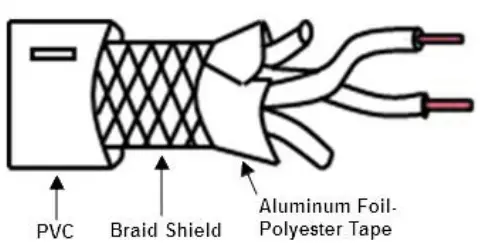 |
| Type | BC (Bare Copper) | |
| Insulation | PE (Polyethylene) | |
| Diameter(inch) | 0.035 | |
| Shield | Aluminum Foil-Polyester,
Tape/Braid Shield |
|
| Capacifance(pF/ft) | 8.5 | |
| Characteristic
impedance(Ω) |
150Ω | |
Parts name and Dimension
This is the front part of the product. Refer to each name when operating the system. For more information, refer to user’s manual.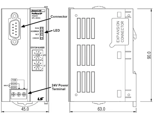
LED details
| LED | Status | Description |
|
RUN |
On | Normal |
| Off | Critical error | |
|
Blink |
1. Ready status
2. Self diagnosis 3. Cable is removed after RUN LED is on 4. I/O module is removed after RUN LED is on 5. I/O module is not installed 6. I/O points exceed the limit 7. The number of I/O module exceeds the limit |
|
| I/O
ERROR |
On | When there is no response in I/O module |
| Off | Normal | |
| NET | On | Normal |
| Off | No data exchange | |
| ERROR | On | Error status |
| Off | Indicates data transmission |
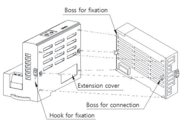
Installing / Removing Modules
- Here is the method to attach each module to the base or remove it.
- Installing module
- When the extension input/output module is installed, pull the two levers of the adapter module up.
- Push the product and connect it agreement with a hook for fixation of four edges and a hook for connection
- After connection, get down the hook for fixation and fix it completely
- Removing module
- Push up the hook for disconnection.
- Detach the product with two hands. (Don’t force it.)
Wiring
- Connector structure and wiring method
- Input line: green line is connected to A1, red line is connected to B1
- Output line: green line is connected to A2, red line is connected to B2
- Connect the shield to the clamp of the shield
- In case of installing the connector at the terminal, install the cable at A1, B1
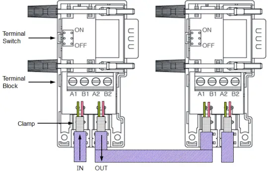
- For more information about wiring, refer to the user manual.
Warranty
- The warranty period is 36 months from the date of manufacture.
- The initial diagnosis of faults should be conducted by the user. However, upon request, LS ELECTRIC or its representative(s) can undertake this task for a fee. If the cause of the fault is found to be the responsibility of LS ELECTRIC, this service will be free of charge.
Exclusions from warranty
- Replacement of consumable and life-limited parts (e.g. relays, fuses, capacitors, batteries, LCDs, etc.)
- Failures or damages caused by improper conditions or handling outside those specified in the user manual
- Failures caused by external factors unrelated to the product
- Failures caused by modifications without LS ELECTRIC’s consent
- Use of the product in unintended ways
- Failures that cannot be predicted/solved by current scientific technology at the time of manufacture
- Failures due to external factors such as fire, abnormal voltage, or natural disasters
- Other cases for which LS ELECTRIC is not responsible
- For detailed warranty information, please refer to the user’s manual.
- The content of the installation guide is subject to change without notice for product performance improvement.
LS ELECTRIC Co., Ltd
- www.ls-electric.com
- E-mail: automation@ls-electric.com
- Headquarters/Seoul Office Tel: 82-2-2034-4033,4888,4703
- LS ELECTRIC Shanghai Office (China) Tel: 86-21-5237-9977
- LS ELECTRIC (Wuxi) Co., Ltd. (Wuxi, China) Tel: 86-510-6851-6666
- LS-ELECTRIC Vietnam Co., Ltd. (Hanoi, Vietnam) Tel: 84-93-631-4099
- LS ELECTRIC Middle East FZE (Dubai, U.A.E.) Tel: 971-4-886-5360
- LS ELECTRIC Europe B.V. (Hoofddorf, Netherlands) Tel: 31-20-654-1424
- LS ELECTRIC Japan Co., Ltd. (Tokyo, Japan) Tel: 81-3-6268-8241
- LS ELECTRIC America Inc. (Chicago, USA) Tel: 1-800-891-2941
- Factory: 56, Samseong 4-gil, Mokcheon-eup, Dongnam-gu, Cheonan-si, Chungcheongnamdo, 31226, Korea

Frequently Asked Questions
Q: What should I do if the device shows an error code?
A: Error codes indicate specific issues with the device. Refer to the user manual to identify the meaning of the error code and follow the recommended actions.
Q: Can I expand the input/output capacity of this PLC?
A: Yes, additional expansion modules are available to increase the input/output capacity of the Programmable Logic Controller. Refer to the product documentation for compatibility and installation instructions.
Documents / Resources
 |
LS XPL-BSSA Programmable Logic Controller [pdf] Installation Guide XPL-BSSA, SIO-8, XPL-BSSA Programmable Logic Controller, Programmable Logic Controller, Logic Controller, Controller |