LS GDL-D22C Programmable Logic Controller
Product Usage Instructions
- Do not contact the terminals while the power is applied.
- Be sure there are no foreign metallic matters.
- Do not manipulate the battery (charge, disassemble, hitting, short, soldering).
- Be sure to check the rated voltage and terminal arrangement before wiring.
- When wiring, tighten the screw of the terminal block with the specified torque range.
- Do not install flammable items in the surroundings. Do not use the PLC in an environment with direct vibration.
- Except for expert service staff, do not disassemble, fix, or modify the product.
- Use the PLC in an environment that meets the general specifications contained in this datasheet.
- Be sure that the external load does not exceed the rating of the output module.
- When disposing of PLC and battery, treat it as industrial waste. I/O signal or communication line shall be wired at least 100mm away from a high-voltage cable or power line.
- The PLC should be operated within a temperature range of -5°C to 70°C and a humidity range of 5%RH to 95%RH.
- Ensure that the PLC is placed in an environment free from direct vibrations and flammable materials.
FAQ
- Q: Can I use the PLC in an environment with high humidity?
- A: The PLC can operate in humidity levels ranging from 5%RH to 95%RH. Ensure proper ventilation and protection from condensation.
- Q: How should I dispose of the PLC and its battery?
- A: When disposing of the PLC and battery, treat them as industrial waste according to local regulations. Do not dispose of them in regular household waste.
- Q: What is the recommended distance for wiring I/O signals or communication lines?
- A: Wire I/O signals or communication lines at least 100mm away from high-voltage cables or power lines to prevent interference or damage.
Programmable Logic Controller Installation Guide
- Smart IO Dnet GDL-D22C,D24C,DT4C/C1 GDL-TR2C/C1,TR4C/C1,RY2C
This installation guide provides simple function information or PLC control. Please read carefully this data sheet and manuals before using products. Especially read precautions then handle the products properly.
Safety Precautions
- Meaning of warning and caution label
WARNING indicates a potentially hazardous situation which, if not avoided, could result in death or serious injury
CAUTION indicates a potentially hazardous situation which, if not avoided, may result in minor or moderate injury. It may also be used to alert against unsafe practices
| WARNING |
| ① Do not contact the terminals while the power is applied.
② Be sure there are no foreign metallic matters. ③ Do not manipulate the battery(charge, disassemble, hitting, short, soldering). |
| CAUTION |
| ① Be sure to check the rated voltage and terminal arrangement before wiring
② When wiring, tighten the screw of the terminal block with the specified torque range ③ Do not install flammable things in surroundings ④ Do not use the PLC in an environment of direct vibration ⑤ Except for expert service staff, do not disassemble fix, or modify the product ⑥ Use the PLC in an environment that meets the general specifications contained in this datasheet. ⑦ Be sure that the external load does not exceed the rating of the output module. ⑧ When disposing of PLC and battery, treat it as industrial waste. ⑨ I/O signal or communication line shall be wired at least 100mm away from a high-voltage cable or power line. |
Operating Environment
- To install, observe the below conditions.
| No | Item | Specification | Standard | ||||
| 1 | Ambient temp. | 0 ~ 55℃ | – | ||||
| 2 | Storage temp. | -25 ~ 70℃ | – | ||||
| 3 | Ambient humidity | 5 ~ 95%RH, non-condensing | – | ||||
| 4 | Storage humidity | 5 ~ 95%RH, non-condensing | – | ||||
| 5 | Vibration Resistance | Occasional vibration | – | – | |||
| Frequency | Acceleration |
IEC 61131-2 |
|||||
| 5≤f<8.4㎐ | – | 3.5mm | 10 times in each direction
for X, Y, Z |
||||
| 8.4≤f≤150㎐ | 9.8㎨(1g) | – | |||||
| Continuous vibration | |||||||
| Frequency | Frequency | Frequency | |||||
| 5≤f<8.4㎐ | – | 1.75mm | |||||
| 8.4≤f≤150㎐ | 4.9㎨(0.5g) | – | |||||
Accessories and Cable Specifications
- Check the DeviceNet Connector attached to the module
- When using the DeviceNet communication channel, the DeviceNet cable shall be used with consideration of communication distance and speed.
| Classification | Thick(class1) | Thick(class2) | Thin(class2) | Remark |
| Type | 7897A | 3082A | 3084A | Maker: Belden |
| Cable Type | Round |
Trunk and Drop lines are used concurrently |
||
| Impedance(Ω) | 120 | |||
| Temperature range(℃) | -20~75 | |||
| Max. allowable current(A) | 8 | 2.4 | ||
| Min. radius of curvature(inch) | 4.4 | 4.6 | 2.75 | |
| Core wire number | 5wires | |||
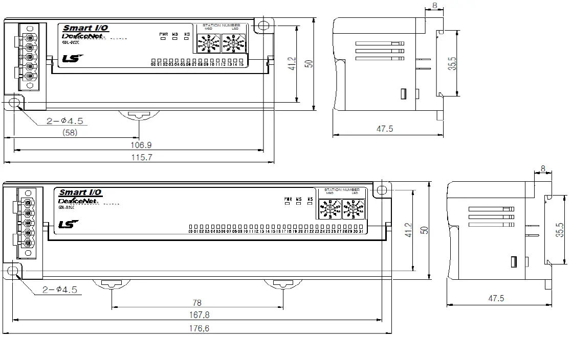
Dimension
Dimension (mm)
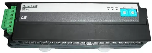
- This is the front part of the product. Refer to each name when operating the system. For more information, refer to the user’s manual.
LED Details
| Name | Description |
| PWR | Displays the status of power |
| MS | Displays the interface status of the communication module |
| NS | Displays the network status of the communication module |
Performance Specifications
- This is the performance specifications of the product. Refer to each name when driving the system. For more information, refer to the user manual.
| Item | GDL-D2xC | GDL-DT4C/C1 | GDL-TRC/C1 | GDL-RY2C |
| Rated Input Current | 5mA | – | – | |
| Rated load voltage | – | DC24V | DC24V/AC220V,
2A/Point, 5A/COM |
|
| Max load | – | 0.5A/Point, 3A/COM | DC 110V, AC 250V
1,200times/hour |
|
| ON Voltage | DC 19V or above | Minimum load voltage/current DC 5V/1mA | ||
| OFF Voltage | DC 6V or less | |||
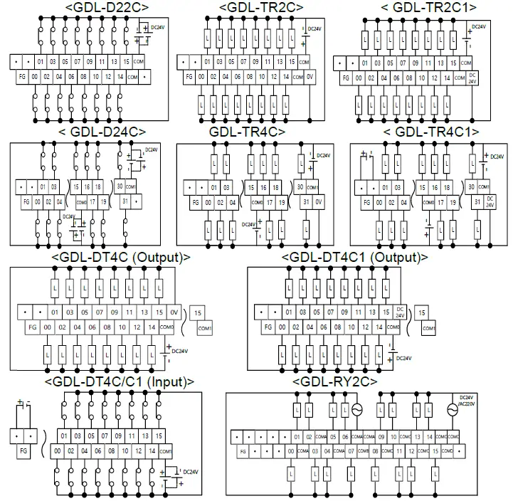
Terminal Block Layout for I/O Wiring
- This is the terminal block layout for I/O wiring.
- Refer to each name when driving the system.
- For more information, refer to the user manual.
Wiring
Wiring for Communication
- 5-pin connector (for external connection)
Signa l Color Service 5 pin connector DC 24V (+) Red Vcc 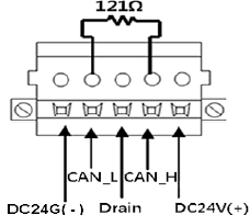
CAN_ H White Signal Drain Bare Shield CAN_ L Blue Signal DC 24V (-) Black GND - For more wiring information, refer to the user manual.
Warranty
- The warranty period is 36 months from the date of manufacture.
- The initial diagnosis of faults should be conducted by the user. However, upon request, LS ELECTRIC or its representative(s) can undertake this task for a fee. If the cause of the fault is found to be the responsibility of LS ELECTRIC, this service will be free of charge.
- Exclusions from warranty
- 1) Replacement of consumable and life-limited parts (e.g. relays, fuses, capacitors, batteries, LCDs, etc.)
- 2) Failures or damages caused by improper conditions or handling outside those specified in the user manual
- 3) Failures caused by external factors unrelated to the product
- 4) Failures caused by modifications without LS ELECTRIC’s consent
- 5) Use of the product in unintended ways
- 6) Failures that cannot be predicted/solved by current scientific technology at the time of manufacture
- 7) Failures due to external factors such as fire, abnormal voltage, or natural disasters
- 8) Other cases for which LS ELECTRIC is not responsible
- For detailed warranty information, please refer to the user’s manual.
- The content of the installation guide is subject to change without notice for product performance improvement.
CONTACT
- LS ELECTRIC Co., Ltd. www.ls-electric.com 10310000309 V4.5 (2024.6)
- E-mail: automation@ls-electric.com
- Headquarters/Seoul Office Tel: 82-2-2034-4033,4888,4703
- LS ELECTRIC Shanghai Office (China) Tel: 86-21-5237-9977
- LS ELECTRIC (Wuxi) Co., Ltd. (Wuxi, China) Tel: 86-510-6851-6666
- LS-ELECTRIC Vietnam Co., Ltd. (Hanoi, Vietnam) Tel: 84-93-631-4099
- LS ELECTRIC Middle East FZE (Dubai, U.A.E.) Tel: 971-4-886-5360
- LS ELECTRIC Europe B.V. (Hoofddorf, Netherlands) Tel: 31-20-654-1424
- LS ELECTRIC Japan Co., Ltd. (Tokyo, Japan) Tel: 81-3-6268-8241
- LS ELECTRIC America Inc. (Chicago, USA) Tel: 1-800-891-2941
- Factory: 56, Samseong 4-gil, Mokcheon-eup, Dongnam-gu, Cheonan-si, Chungcheongnamdo, 31226, Korea

Documents / Resources
 |
LS GDL-D22C Programmable Logic Controller [pdf] Installation Guide D24C, DT4C-C1, GDL-TR2C-C1, TR4C-C1, RY2C, GDL-D22C Programmable Logic Controller, GDL-D22C, Programmable Logic Controller, Logic Controller, Controller |