Fronius RI FB Inside i Bus Module

Product Usage Instructions
Safety
Read and understand all safety regulations before operating the device.
LEDs on the Robot Interface
The LEDs on the robot interface serve different diagnostic purposes:
- LED ETH1: Description
- LED ETH2: Description
- LED 3: Description
- LED 4: Description
- LED 5: Description
- LED 6: Description
- LED +3V3: Description
- LED +24V: Description
Configuring the Robot Interface
Function of the DIP Switch on the Interface
The DIP switch on the robot interface is used to configure:
- The width of the process data
- The node address/IP address
Configuring the Process Data Width
DIP Switch Configuration:
| DIP Switch Position | Configuration |
|---|---|
| OFF OFF – – – – – – | Standard Image 320 Bit |
| OFF ON – – – – – – | Economy Image 128 Bit |
| ON OFF – – – – – ON ON – – – – – – | Not used |
Setting the Node Address with DIP Switch (Example)
DIP Switch Configuration:
| DIP Switch Position | Node Address Setting |
|---|---|
| OFF OFF OFF OFF OFF OFF ON | Address 1234567 |
FAQs
Q: What do the blinking frequencies of LEDs indicate?
A: The blinking frequencies of LEDs indicate different network connection statuses:
- Blinking with 4 Hz: No connection to SpeedNet.
- Blinking with 20 Hz: Connection to SpeedNet is being established.
General
Device Concept
The robot interface serves as an interface between the power source and standardized bus modules supporting a wide range of communication protocols. Fronius may factory-fit the robot interface in the power source but it can also be retrofitted by appropriately trained and qualified personnel.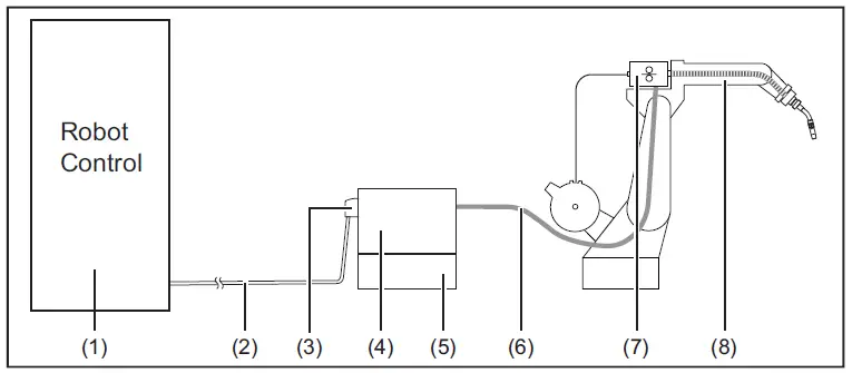
- Robot control system
- SpeedNet data cable
- Robot interface
- Power source
- Cooling unit
- Interconnecting hose pack
- Wire feeder
- Robot
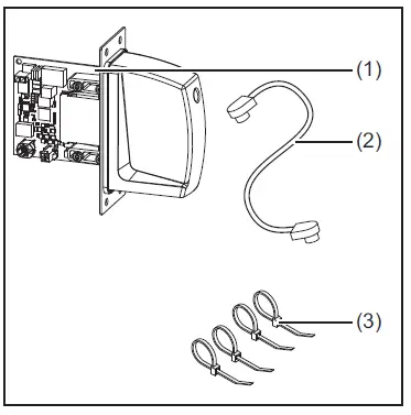
Scope of supply
- RI FB Inside/i
- Data cable 4-pin
- 4 cable ties
- These Operating Instructions (not pictured)
Environmental Conditions
CAUTION!
A risk is posed by prohibited environmental conditions.
- This can result in severe damage to equipment.
- Only store and operate the device under the following environmental conditions.
Temperature range of ambient air:
- During operation: -10 °C to +40 °C (14 °F to 104 °F)
- During transport and storage: -20 °C to +55 °C (-4 °F to 131 °F)
Relative humidity:
- Up to 50% at 40 °C (104 °F)
- Up to 90% at 20 °C (68 °F)
Ambient air: free of dust, acids, corrosive gases or substances, etc.
Altitude above sea level: up to 2000 m (6500 ft).
Technical data
- Power supply Internal (24 V)
- Protection class IP 23
Safety
WARNING!
- Danger from incorrect operation and work that is not carried out properly.
- Serious injury and damage to property may result.
- All the work and functions described in this document must only be carried out by trained and qualified personnel.
- Read and understand this document.
- Read and understand all the Operating Instructions for the system components, especially the safety rules.
WARNING!
- Danger from unplanned signal transmission.
- Serious injury and damage to property may result.
- Do not transfer safety signals via the interface.
Connection
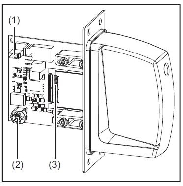
Connection Sockets and Indicators on the Robot Interface
Connections on the robot inter-face
- Power supply connection 2- pin
- SpeedNet data cable connec-tion 4- pin
- Bus module connection
LEDs on robot interface PCB
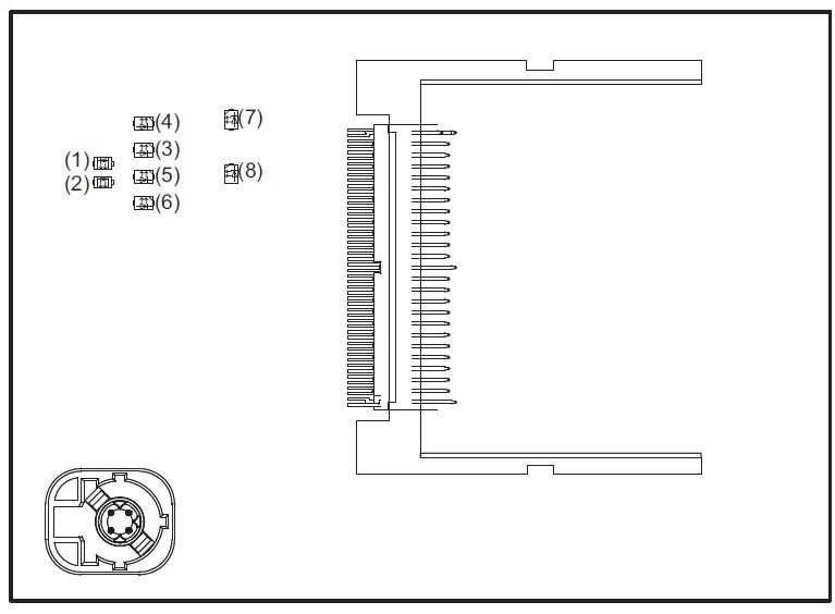
| (1) | ETH1 LED | Green | For diagnosing the network connection.
For details, see section below titled “LEDs for network connection diagnosis” |
| (2) | ETH2 LED | Orange | |
| (3) | LED 3 | Green | No function |
| (4) | LED 4 | Green | |
| (5) | LED 5 | Green |
|
| (6) | LED 6 | Red | Lights up when an internal error occurs.
Remedy: Restart the robot interface. If this does not resolve the issue, inform the service team. |
| (7) | +3V3 LED | Green | For diagnosing the power supply. For details, see section below titled “LEDs for power supply diagnosis” |
| (8) | +24V LED | Green |
LEDs for power supply diagnosis
| LED | Display | Meaning | Cause |
| +24V | Off | No supply voltage available for interface |
|
| Lights up | 24 VDC supply voltage present on robot interface | ||
| +3V3 | Off | No operating voltage present on robot interface |
|
| Lights up | 3 VDC operating voltage present on robot interface |
LEDs for Network Connection Diagnosis
| LED | Indicator | Meaning | Cause |
| ETH1 | Off | No network connection |
|
| Lights up | Network connection established | ||
| Flashes | Data transfer in progress | ||
| ETH2 | Off | Transmission speed 10 Mbit/s | |
| Lights up | Transmission speed 100 Mbit/s |
Configuration of robot interface
Function of the DIP switch on the interface
The DIP switch on the robot interface is used to configure:
- the process data width
- the node address/IP address
Factory default: all positions of the DIP switch are in the OFF position. This corresponds to the binary value 0.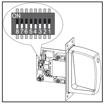
NOTE!
- Risk due to invalid DIP switch settings.
- This may result in malfunctions.
- Every time you change the DIP switch settings, re-start the interface after-wards. This is essential for the changes to take effect.
- Interface re-start = disconnect and reconnect the power supply or execute the corresponding function on the power source website (SmartManager).
Configuration of the process data width
| Dip switch | Configuration | |||||||
| 8 | 7 | 6 | 5 | 4 | 3 | 2 | 1 | |
| OFF | OFF | – | – | – | – | – | – | Standard image 320 Bit |
| OFF | ON | – | – | – | – | – | – | Economy image 128 Bit |
| ON | OFF | – | – | – | – | – | – | Retro Fit
Scope dependent on bus module |
| ON | ON | – | – | – | – | – | – | Not used |
The process data width defines the scope of the transferred data volume.
The kind of data volume that can be transferred depends on
- the robot controls
- the number of power sources
- the type of power sources
- “Intelligent Revolution”
- “Digital Revolution” (Retro Fit)
Set node address with dip switch (example)
| Dip switch | Node address | |||||||
| 8 | 7 | 6 | 5 | 4 | 3 | 2 | 1 | |
| – | – | OFF | OFF | OFF | OFF | OFF | ON | 1 |
| – | – | OFF | OFF | OFF | OFF | ON | OFF | 2 |
| – | – | OFF | OFF | OFF | OFF | ON | ON | 3 |
| – | – | ON | ON | ON | ON | ON | OFF | 62 |
| – | – | ON | ON | ON | ON | ON | ON | 63 |
- The node address is set with positions 1 to 6 of the dip switch.
- The configuration is carried out in binary format. This results in a configuration range of 1 to 63 in decimal format
NOTE!
After every change of the configurations of the dip switch settings, the interface needs to be restarted so that the changes will take effect.
(Restart = interrupting and restoring the power supply or executing the relevant function on the website of the power source)
Installing the Robot Interface
Safety
WARNING!
- Danger from electric current.
- This can result in serious injuries and death.
- Before starting work, switch off all the devices and components involved and disconnect them from the grid.
- Secure all devices and components involved so they cannot be switched back on.
- After opening the device, use a suitable measuring instrument to check that electrically charged components (such as capacitors) have been discharged.
WARNING!
- Danger from electrical current due to inadequate ground conductor connection.
- This can result in serious injury and damage to property.
- Always use the original housing screws in the original quantity.
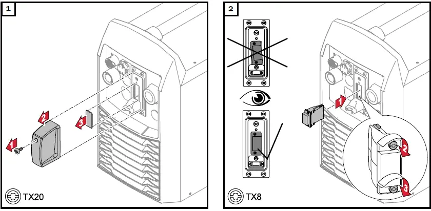
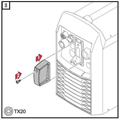
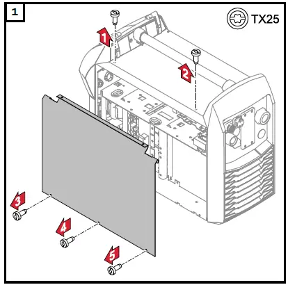
Preparation
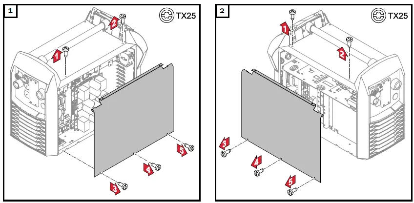
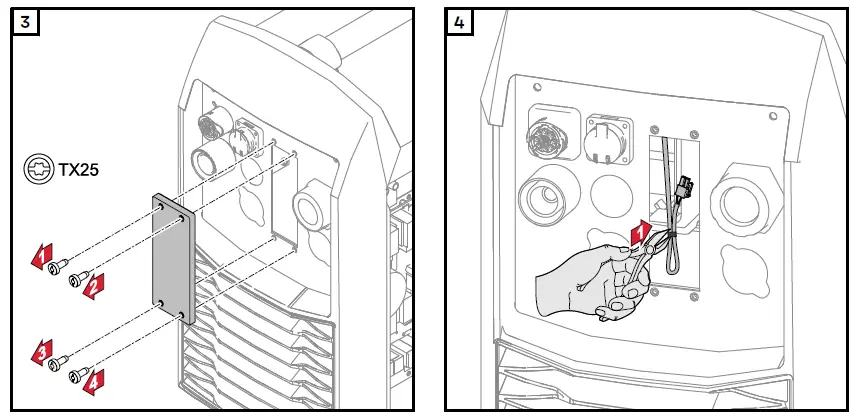
- Remove cable tie from power supply cable
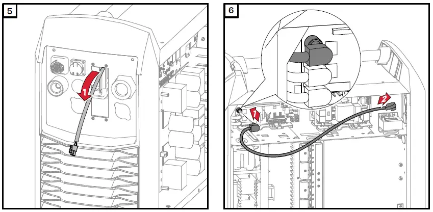
- Lead the power supply cable out of the power source
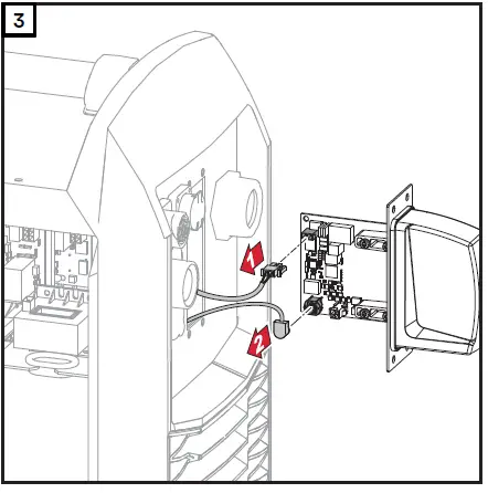
- Connect and install data cable

- Lead the data cable out of the power source
- Secure the data cable with cable ties
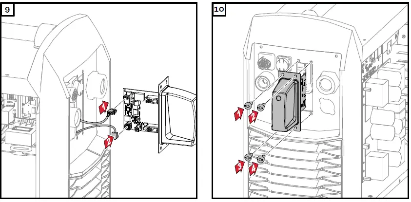
Installing the bus module in the robot interface
Safety
WARNING!
- Danger from electrical current.
- Serious injuries or death may result.
- Before starting work, switch off all devices and components involved, and disconnect them from the grid.
- Secure all devices and components involved so that they cannot be switched back on.
WARNING!
- Danger from electrical current due to inadequate ground conductor connection.
- Serious personal injury and property damage may result.
- Always use the original housing screws in the quantity initially supplied.
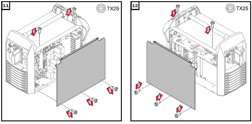
Installing the Bus Module
Removing the robot interface
Safety
WARNING!
- Danger from electric current.
- This can result in serious injuries and death.
- Before starting work, switch off all the devices and components involved and disconnect them from the grid.
- Secure all devices and components involved so they cannot be switched back on.
- After opening the device, use a suitable measuring instrument to check that electrically charged components (such as capacitors) have been discharged.
WARNING!
- Danger from electrical current due to inadequate ground conductor connection.
- This can result in serious injury and damage to property.
- Always use the original housing screws in the original quantity.
Preparation
Removing the robot interface

Final tasks

Removing the bus module


- Fronius International GmbH
- FroniusstraBe 1
- 4643 Pettenbach
- Austria
- contact@fronius.com
- www.fronius.com
At www.fronius.com/contact you will find the contact details of all Fronius subsidiaries and Sales & Service Partners.
Documents / Resources
 |
Fronius RI FB Inside i Bus Module [pdf] Instruction Manual 42, 0410, 1912, RI FB Inside i Bus Module, RI FB Inside i, Bus Module, Module |


