Fronius RI FB PRO/i Bus Module Ip Address
Specifications
- Vendor: Fronius International GmbH
- Device Type: Communication adapter
- Product Code: 1056 decimal (0420 hex)
- Product Name: Fronius FB Pro DeviceNet
Product Information
The RI FB PRO/i RI MOD/i CC-M40 DeviceNet is a communication adapter designed for use with specific robot controllers. It allows for communication between the robot controller and other devices via the DeviceNet protocol.
Product Usage Instructions
Setting Node Address
To set the node address of the bus module:
- Locate the DIP switch on the interface.
- Adjust the DIP switch positions to set the node address within the range of 1 to 63.
- Factory default: all DIP switch positions are set to OFF.
Setting Process Data Width
To set the process data width of the bus module:
- Refer to the section on setting process data width on page 9.
Data Types and Addressing
The following data types are used:
- UINT16 (Unsigned Integer): Range from 0 to 65535
- SINT16 (Signed Integer): Range from -32768 to 32767
Addresses are specified relatively and absolutely for different signals and functions as detailed in the user manual.
Frequently Asked Questions (FAQ)
- Q: What is the default node address setting?
A: The default node address setting for the bus module is 1. - Q: How many stations can be connected to the network?
A: The maximum number of stations that can be connected is 64 participants.
General
Safety
WARNING!
Danger from incorrect operation and work that is not carried out properly. This can result in serious personal injury and damage to property.
- All the work and functions described in this document must only be carried out by technically trained and qualified personnel.
- Read and understand this document in full.
- Read and understand all safety rules and user documentation for this equipment and all system components.
Connections and Indicators
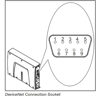
| Pin | Signal | Description |
| 1 | – | – |
| 2 | CAN_L | CAN low bus line |
| 3 | V- | Supply voltage |
| 4 | – | – |
| 5 | – | – |
| 6 | GND | Ground |
| 7 | CAN_H | CAN high bus line |
| 8 | – | – |
| 9 | V+ | Supply voltage |
| Housing = cable shielding: GND is connected internally with the cable shielding. A terminating resistor is located internally between the CAN_L and CAN_H signals. | ||
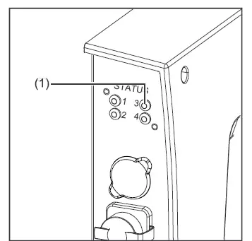
| (1) MS LED – module status |
| Off: No supply voltage |
| Lights up green: Normal operation |
| Flashes green: Missing or incomplete configuration, commissioning required |
| Lights up red: Non-correctable error |
| Flashes red: Correctable error |
| Alternates between red and green: Self-test is running |
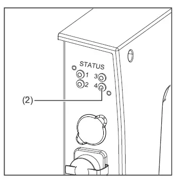
| (2) NS LED – network status |
| Off: Not online or no supply voltage |
| Lights up green: Online, one or more connections established |
| Flashes green: Online, no connections established |
| Lights up red: Critical connection error |
| Flashes red: Timeout for one or more of the connections |
| Alternates between red and green: Self-test is running |
Data Transfer Properties
Network topology
Linear bus, bus termination on both ends (121 Ohm), stub cables are possible
Medium and maximum bus length
When selecting the cable, plug, and terminating resistors, the ODVA recommendation for the planning and installation of DeviceNet systems must be observed.
Number of stations
Max. 64 participants
Transmission speed
500 kbit/s, 250 kbit/s, 125 kbit/s
Process data width
See section Setting the process data width of the bus module on
Configuration Parameters
In some robot control systems, it may be necessary to state the configuration parameters described here so that the bus module can communicate with the robot.
| Parameter | Value | Description |
| Vendor ID | 0534hex (1332dec) | Fronius International GmbH |
| Device Type | 000Chex (12dec) | Communication adapter |
| Product Code | 0420hex (1056dec) | Fronius FB Pro DeviceNet |
Product Name Fronius-FB-Pro-DeviceNet(TM)
Setting the Bus Module Node Address
You can set the bus module node address as follows:
- Using the DIP switch in the interface within the range 1 to 63
- All positions are set to the OFF position at the factory. In this case, the IP address must be set on the website of the welding machine
- On the website of the welding machine within the range 1 to 126 (if all positions of the DIP switch are set to the OFF position)
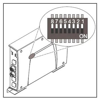
| Example for setting the node address of the bus module using the DIP switch in the interface: | ||||||||
| Dip switch |
Node address |
|||||||
| 8 | 7 | 6 | 5 | 4 | 3 | 2 | 1 | |
| – | – | OFF | OFF | OFF | OFF | OFF | ON | 1 |
| – | – | OFF | OFF | OFF | OFF | ON | OFF | 2 |
| – | – | OFF | OFF | OFF | OFF | ON | ON | 3 |
| – | – | ON | ON | ON | ON | ON | OFF | 62 |
| – | – | ON | ON | ON | ON | ON | ON | 63 |
- The node address is set with positions 1 to 6 of the dip switch.
- The configuration is carried out in binary format. This results in a configuration range of 1 to 63 in decimal format.
- Setting the node address on the website of the welding machine:
Note down the IP address of the welding machine used:
- On the welding machine control panel, select “Defaults”
- On the welding machine control panel, select “System”
- On the welding machine control panel, select “Information” 4 Note down the displayed IP address (example: 10.5.72.13)
- Access website of the welding machine in the internet browser:
- Connect the computer to the network of the welding machine
- Enter the IP address of the welding machine in the search bar of the internet browser and confirm
- Enter the standard user name (admin) and password (admin)
- The website of the welding machine is displayed
Set the bus module node address:
- The website of the welding machine is displayed
- On the welding machine website, select the “RI FB PRO/i” tab
- Enter the desired node address for the interface under “Module configuration”
For example: 2 - Select “Set configuration”
- Select “Restart module”
- The set node address is applied
Set the Process Data Width of the Bus Module
Setting the process data width of the bus module
Note down the IP address of the welding machine used:
- On the welding machine control panel, select “Defaults”
- On the welding machine control panel, select “System”
- On the welding machine control panel, select “Information” 4 Note down the displayed IP address (example: 10.5.72.13)
- Open website of the welding machine in the internet browser:
- Connect the computer to the network of the welding machine
- Enter the IP address of the welding machine in the search bar of the internet browser and confirm
- Enter the standard user name (admin) and password (admin)
- The website of the welding machine is displayed
- Set the process data width of the bus module:
- On the welding machine website, select the “RI FB PRO/i” tab
- Under “Process data”, select the desired process data configuration
- Select “Save”
- The field bus connection is restarted and the configuration is applied
Input and output signals
Data types
The following data types are used:
- UINT16 (Unsigned Integer) Whole number in the range from 0 to 65535
- SINT16 (Signed Integer) Whole number in the range from -32768 to 32767
Conversion examples:
- for a positive value (SINT16) e. g. desired wire speed x factor 12.3 m/min x 100 = 1230dec = 04CEhex
- for a negative value (SINT16) e. g. arc correction x factor -6.4 x 10 = -64dec = FFC0hex
Availability of input signals
The input signals listed below are available from firmware V2.0.0 of the RI FB PRO/i onwards.
Input signals (from robot to power source)
| Address | Signal | Activity/data type | Range | Factor | Process image | ||||
| Relative | Absolute | Standard | Economy | ||||||
| WORD | BYTE | BIT | BIT | ||||||
| 0 | 0 | 0 | 0 | Welding Start | Increasing | √ | √ | ||
| 1 | 1 | Robot ready | High | ||||||
| 2 | 2 | Working mode Bit 0 | High | See table Value Range for Working Mode on page 35 | |||||
| 3 | 3 | Working mode Bit 1 | High | ||||||
| 4 | 4 | Working mode Bit 2 | High | ||||||
| 5 | 5 | Working mode Bit 3 | High | ||||||
| 6 | 6 | Working mode Bit 4 | High | ||||||
| 7 | 7 | — | |||||||
| 1 | 0 | 8 | Gas on | Increasing | |||||
| 1 | 9 | Wire forward | Increasing | ||||||
| 2 | 10 | Wire backward | Increasing | ||||||
| 3 | 11 | Error quit | Increasing | ||||||
| 4 | 12 | Touch sensing | High | ||||||
| 5 | 13 | Torch blow out | Increasing | ||||||
| 6 | 14 | Processing selection Bit 0 | High | See table selection on page 36Value range Process li ne | |||||
| 7 | 15 | Processline selection Bit 1 | High | ||||||
| Address | Signal | Activity/data type | Range | Factor | Process image | ||||
| Relative | Absolu- te | Standard | Economy | ||||||
| WORD | BYTE | BIT | BIT | ||||||
| 1 | 2 | 0 | 16 | Welding simulation | High | √ | √ | ||
| 1 | 17 | Welding process MIG/MAG: 1) Synchro pulse on | High | ||||||
| Welding process WIG: 2) TAC on | High | ||||||||
| 2 | 18 | Welding process WIG: 2) Cap shaping | High | ||||||
| 3 | 19 | — | |||||||
| 4 | 20 | — | |||||||
| 5 | 21 | Booster manual | High | ||||||
| 6 | 22 | Wire brake on | High | ||||||
| 7 | 23 | Torchbody Xchange | High | ||||||
| 3 | 0 | 24 | — | ||||||
| 1 | 25 | Teach mode | High | ||||||
| 2 | 26 | — | |||||||
| 3 | 27 | — | |||||||
| 4 | 28 | — | |||||||
| 5 | 29 | Wire since start | Increasing | ||||||
| 6 | 30 | Wire sense break | Increasing | ||||||
| 7 | 31 | — | |||||||
| Address | Signal | Activity/data type | Range | Factor | Process image | ||||
| Relative | Absolu- te | Standard | Economy | ||||||
| WORD | BYTE | BIT | BIT | ||||||
| 2 | 4 | 0 | 32 | TWIN mode Bit 0 | High | See table Value Range for TWIN Mode on page 36 | √ | √ | |
| 1 | 33 | TWIN mode Bit 1 | High | ||||||
| 2 | 34 | — | |||||||
| 3 | 35 | — | |||||||
| 4 | 36 | — | |||||||
| 5 | 37 | Documentation mode | High | See table Value Range for Documentation Mode on page 36 | |||||
| 6 | 38 | — | |||||||
| 7 | 39 | — | |||||||
| 5 | 0 | 40 | — | ||||||
| 1 | 41 | — | |||||||
| 2 | 42 | — | |||||||
| 3 | 43 | — | |||||||
| 4 | 44 | — | |||||||
| 5 | 45 | — | |||||||
| 6 | 46 | — | |||||||
| 7 | 47 | Disable process-controlled correction | High | ||||||
| Address | Signal | Activity/data type | Range | Factor | Process image | ||||
| Relative | Absolu- te | Standard | Economy | ||||||
| WORD | BYTE | BIT | BIT | ||||||
| 3 | 6 | 0 | 48 | — | √ | √ | |||
| 1 | 49 | — | |||||||
| 2 | 50 | — | |||||||
| 3 | 51 | — | |||||||
| 4 | 52 | — | |||||||
| 5 | 53 | — | |||||||
| 6 | 54 | — | |||||||
| 7 | 55 | — | |||||||
| 7 | 0 | 56 | ExtInput1 => OPT_Output 1 | High | |||||
| 1 | 57 | ExtInput2 => OPT_Output 2 | High | ||||||
| 2 | 58 | ExtInput3 => OPT_Output 3 | High | ||||||
| 3 | 59 | ExtInput4 => OPT_Output 4 | High | ||||||
| 4 | 60 | ExtInput5 => OPT_Output 5 | High | ||||||
| 5 | 61 | ExtInput6 => OPT_Output 6 | High | ||||||
| 6 | 62 | ExtInput7 => OPT_Output 7 | High | ||||||
| 7 | 63 | ExtInput8 => OPT_Output 8 | High | ||||||
| 4 | 8-9 | 0–7 | 64–79 | Welding characteristic- / Job number | UINT16 | 0 to 1000 | 1 | √ | √ |
| 5 | 10- 11 | 0-7 | 80-95 | Welding process MIG/MAG: 1)Constant Wire: Wire feed speed command value | SINT16 | -327,68 to327,67[m/min] | 100 | √ | √ |
| Welding process WIG: 2) Main- / Hotwire current command value | UINT16 | 0 to6553,5 [A] | 10 | ||||||
| For job-mode: Power correction |
SINT16 |
-20,00 to
20,00 [%] |
100 |
||||||
| Address | Signal | Activity/data type | Range | Factor | Process image | ||||
| Relative | Absolu- te | Standard | Economy | ||||||
| WORD | BYTE | BIT | BIT | ||||||
| 6 | 12- 13 | 0-7 | 96-111 | Welding process MIG/MAG: 1) Arclength correction | SINT16 | -10,0 to10,0[Schritte] | 10 | √ | √ |
| Welding processing/MAG Standard-Manuel: Welding voltage | UINT16 | 0,0 to6553,5 [V] | 10 | ||||||
| Welding process WIG: 2) Wire feed speed command value | SINT16 | -327,68 to327,67[m/min] | 100 | ||||||
| For job-mode: Arclength correction | SINT16 | -10,0 to10,0[Schritte] | 10 | ||||||
| Welding process Constant Wire: Hotwire current | UINT16 | 0,0 to6553,5 [A] | 10 | ||||||
| 7 | 14- 15 | 0-7 | 112-127 | Welding process MIG/MAG: 1) Pulse-/dynamic correction | SINT16 | -10,0 to10,0[steps] | 10 | √ | √ |
| Welding processing/MAG Standard-Manuel: Dynamic | UINT16 | 0,0 to10,0[steps] | 10 | ||||||
| Welding process WIG: 2) Wire correction | SINT16 | -10,0 to10,0[steps] | 10 | ||||||
| 8 | 16- 17 | 0-7 | 128-143 | Welding process MIG/MAG: 1) Wire retract correction | UINT16 | 0,0 to10,0[steps] | 10 | √ | |
| Welding process WIG: 2) Wire retract end | UINT16 | OFF, 1 to50[mm] | 1 | ||||||
| 9 | 18- 19 | 0-7 | 144-159 | Welding speed | UINT16 | 0,0 to1000,0[cm/min] | 10 | √ | |
| Address | Signal | Activity/data type | Range | Factor | Process image | ||||
| Relative | Absolu- te | Standard | Economy | ||||||
| WORD | BYTE | BIT | BIT | ||||||
| 10 | 20- 21 | 0-7 | 160-175 | Process controlled correction | See table Value range for Process controlled correction on page 36 | √ | |||
| 11 | 22- 23 | 0-7 | 176-191 | Welding process WIG: 2) Wire positioning start | √ | ||||
| 12 | 24- 25 | 0-7 | 192-207 | — | √ | ||||
| 13 | 26- 27 | 0-7 | 208-223 | — | √ | ||||
| 14 | 28- 29 | 0-7 | 224-239 | — | √ | ||||
| 15 | 30- 31 | 0-7 | 240-255 | Wire forward / backward length | UINT16 | OFF / 1 to 65535[mm] | 1 | √ | |
| 16 | 32- 33 | 0-7 | 256-271 | Wire sense edge detection | UINT16 | OFF / 0,5to 20,0 [mm] | 10 | √ | |
| 17 | 34- 35 | 0-7 | 272-287 | — | √ | ||||
| 18 | 36- 37 | 0-7 | 288-303 | — | √ | ||||
| 19 | 38- 39 | 0-7 | 304-319 | Seam number | UINT16 | 0 to65535 | 1 | √ | |
- MIG/MAG Puls-Synergic, MIG/MAG Standard-Synergic, MIG/MAG Stan-dard-Manuel, MIG/MAG PMC, MIG/MAG, LSC
- WIG coldwire, WIG hotwire
Value Range for Working Mode
| Bit 4 | Bit 3 | Bit 2 | Bit 1 | Bit 0 | Description |
| 0 | 0 | 0 | 0 | 0 | Internal parameter selection |
| 0 | 0 | 0 | 0 | 1 | Special 2-step mode characteristics |
| 0 | 0 | 0 | 1 | 0 | Job mode |
| Bit 4 | Bit 3 | Bit 2 | Bit 1 | Bit 0 | Description |
| 0 | 1 | 0 | 0 | 0 | 2-step mode characteristics |
| 0 | 1 | 0 | 0 | 1 | 2-step MIG/MAG standard manual |
| 1 | 0 | 0 | 0 | 0 | Idle Mode |
| 1 | 0 | 0 | 0 | 1 | Stop coolant pump |
| 1 | 1 | 0 | 0 | 1 | R/L-Measurement |
Value range for operating mode
Value Range for Documentation Mode
| Bit 0 | Description |
| 0 | Seam number of welding machine (internal) |
| 1 | Seam number of robot (Word 19) |
Value range for documentation mode
Value Range for TWIN Mode
| Bit 1 | Bit 0 | Description |
| 0 | 0 | TWIN Single mode |
| 0 | 1 | TWIN Lead mode |
| 1 | 0 | TWIN Trail mode |
| 1 | 1 | Reserved |
Value range for documentation mode
Value Range for TWIN Mode
| Process | Signal |
Activity/data type |
Value range configuration range |
Unit |
Factor |
| PMC | Arc length stabilizer | SINT16 | -327.8 to +327.7 0.0 to +5.0 |
Volts |
10 |
Value range for TWIN mode
Value Range for Documentation Mode
| Bit 1 | Bit 0 | Description |
| 0 | 0 | Process line 1 (default) |
| 0 | 1 | Process line 2 |
| 1 | 0 | Process line 3 |
| 1 | 1 | Reserved |
Value range for process line selection
Availability of the output signals
The output signals listed below are available from firmware V2.0.0 of the RI FB PRO/i onwards.
Output Signals (from Power Source to Robot)
| Address | Signal | Activity/data type | Range | Factor | Process image | ||||
| relative | absolute | Standard | Economy | ||||||
| WORD | BYTE | BIT | BIT | ||||||
| 0 | 0 | 0 | 0 | Heartbeat Powersource | High/Low | 1 Hz | √ | √ | |
| 1 | 1 | Power source ready | High | ||||||
| 2 | 2 | Warning | High | ||||||
| 3 | 3 | Process active | High | ||||||
| 4 | 4 | Current flow | High | ||||||
| 5 | 5 | Arc stable- / touch signal | High | ||||||
| 6 | 6 | Main current signal | High | ||||||
| 7 | 7 | Touch signal | High | ||||||
| 1 | 0 | 8 | Collision box active | High | 0 = collision- on or cable break | ||||
| 1 | 9 | Robot Motion Release | High | ||||||
| 2 | 10 | Wire stick workpiece | High | ||||||
| 3 | 11 | — | |||||||
| 4 | 12 | Short circuit contact tip | High | ||||||
| 5 | 13 | Parameter selection internally | High | ||||||
| 6 | 14 | Characteristic number valid | High | ||||||
| 7 | 15 | Torch body gripped | High | ||||||
| Address | Signal | Activity/data type | Range | Factor | Process image | ||||
| relative | absolute | Standard | Economy | ||||||
| WORD | BYTE | BIT | BIT | ||||||
| 1 | 2 | 0 | 16 | Command value out of range | High | √ | √ | ||
| 1 | 17 | Correction out of range | High | ||||||
| 2 | 18 | — | |||||||
| 3 | 19 | Limitsignal | High | ||||||
| 4 | 20 | — | |||||||
| 5 | 21 | — | |||||||
| 6 | 22 | Main supply status | Low | ||||||
| 7 | 23 | — | |||||||
| 3 | 0 | 24 | Sensor status 1 | High | See table Assignment of Sensor Statuses 1–4 on page 40 | ||||
| 1 | 25 | Sensor status 2 | High | ||||||
| 2 | 26 | Sensor status 3 | High | ||||||
| 3 | 27 | Sensor status 4 | High | ||||||
| 4 | 28 | — | |||||||
| 5 | 29 | — | |||||||
| 6 | 30 | — | |||||||
| 7 | 31 | — | |||||||
| 2 | 4 | 0 | 32 | — | √ | √ | |||
| 1 | 33 | — | |||||||
| 2 | 34 | — | |||||||
| 3 | 35 | Safety status Bit 0 | High | See table Value range Safety status on page 41 | |||||
| 4 | 36 | Safety status Bit 1 | High | ||||||
| 5 | 37 | — | |||||||
| 6 | 38 | Notification | High | ||||||
| 7 | 39 | System not ready | High | ||||||
| 5 | 0 | 40 | — | ||||||
| 1 | 41 | — | |||||||
| 2 | 42 | — | |||||||
| 3 | 43 | — | |||||||
| 4 | 44 | — | |||||||
| 5 | 45 | — | |||||||
| 6 | 46 | — | |||||||
| 7 | 47 | — | |||||||
| Address | Signal | Activity/data type | Range | Factor | Process image | ||||
| relative | absolute | Standard | Economy | ||||||
| WORD | BYTE | BIT | BIT | ||||||
| 3 | 6 | 0 | 48 | Process Bit 0 | High | See table Value Range for Process Bit on page 41 | √ | √ | |
| 1 | 49 | Process Bit 1 | High | ||||||
| 2 | 50 | Process Bit 2 | High | ||||||
| 3 | 51 | Process Bit 3 | High | ||||||
| 4 | 52 | Process Bit 4 | High | ||||||
| 5 | 53 | — | |||||||
| 6 | 54 | Touch signal gas nozzle | High | ||||||
| 7 | 55 | TWIN synchronization active | High | ||||||
| 7 | 0 | 56 | ExtOutput1 <= OPT_Input1 | High | |||||
| 1 | 57 | ExtOutput2 <= OPT_Input2 | High | ||||||
| 2 | 58 | ExtOutput3 <= OPT_In put3 | High | ||||||
| 3 | 59 | ExtOutput4 <= OPT_Input4 | High | ||||||
| 4 | 60 | ExtOutput5 <= OPT_In put5 | High | ||||||
| 5 | 61 | ExtOutput6 <= OPT_Input6 | High | ||||||
| 6 | 62 | ExtOutput7 <= OPT_Input7 | High | ||||||
| 7 | 63 | ExtOutput8 <= OPT_Input8 | High | ||||||
| 4 | 8-9 | 0-7 | 64-79 | Welding voltage | UINT16 | 0.0 to655.35 [V] | 100 | √ | √ |
| 5 | 10- 11 | 0-7 | 80-95 | Welding current | UINT16 | 0.0 to 6553.5 [A] | 10 | √ | √ |
| 6 | 12- 13 | 0-7 | 96-111 | Wire feed speed | SINT16 | -327.68 to327.67 [m/ min] | 100 | √ | √ |
| 7 | 14- 15 | 0-7 | 112-127 | Actual real value for seam tracking | UINT16 | 0 to6.5535 | 10000 | √ | √ |
| 8 | 16- 17 | 0-7 | 128-143 | Error number | UINT16 | 0 to65535 | 1 | √ | |
| 9 | 18- 19 | 0-7 | 144-159 | Warning number | UINT16 | 0 to65535 | 1 | √ | |
| Address | Signal | Activity/data type | Range | Factor | Process image | ||||
| relative | absolute | Standard | Economy | ||||||
| WORD | BYTE | BIT | BIT | ||||||
| 10 | 20- 21 | 0-7 | 160-175 | Motor current M1 | SINT16 | -327.68 to327.67 [A] | 100 | √ | |
| 11 | 22- 23 | 0-7 | 176-191 | Motor current M2 | SINT16 | -327.68 to327.67 [A] | 100 | √ | |
| 12 | 24- 25 | 0-7 | 192-207 | Motor current M3 | SINT16 | -327.68 to327.67 [A] | 100 | √ | |
| 13 | 26- 27 | 0-7 | 208-223 | — | √ | ||||
| 14 | 28- 29 | 0-7 | 224-239 | — | √ | ||||
| 15 | 30- 31 | 0-7 | 240-255 | — | √ | ||||
| 16 | 32- 33 | 0-7 | 256-271 | Wire position | SINT16 | -327.68 to327.67[mm] | 100 | √ | |
| 17 | 34- 35 | 0-7 | 272-287 | — | √ | ||||
| 18 | 36- 37 | 0-7 | 288-303 | — | √ | ||||
| 19 | 38- 39 | 0-7 | 304-319 | — |
√ |
||||
Assignment of Sensor Statuses 1–4
| Signal | Description |
| Sensor status 1 | OPT/i WF R wire end (4,100,869) |
| Sensor status 2 | OPT/i WF R wire drum (4,100,879) |
| Sensor status 3 | OPT/i WF R ring sensor (4,100,878) |
| Sensor status 4 | Wire buffer set CMT TPS/i (4,001,763) |
Assignment of sensor statuses
Value range Safety status
| Bit 1 | Bit 0 | Description |
| 0 | 0 | Reserve |
| 0 | 1 | Hold |
| 1 | 0 | Stop |
| 1 | 1 | Not installed / active |
Value range Safety status
Value Range for Process Bit
| Bit 4 | Bit 3 | Bit 2 | Bit 1 | Bit 0 | Description |
| 0 | 0 | 0 | 0 | 0 | No internal parameter selection or process |
| 0 | 0 | 0 | 0 | 1 | MIG/MAG pulse synergic |
| 0 | 0 | 0 | 1 | 0 | MIG/MAG standard synergic |
| 0 | 0 | 0 | 1 | 1 | MIG/MAG PMC |
| 0 | 0 | 1 | 0 | 0 | MIG/MAG LSC |
| 0 | 0 | 1 | 0 | 1 | MIG/MAG standard manual |
| 0 | 0 | 1 | 1 | 0 | Electrode |
| 0 | 0 | 1 | 1 | 1 | TIG |
| 0 | 1 | 0 | 0 | 0 | CMT |
| 0 | 1 | 0 | 0 | 1 | Constantine |
| 0 | 1 | 0 | 1 | 0 | ColdWire |
| 0 | 1 | 0 | 1 | 1 | Dynamic Wire |
Value Range for Process Bit
Value Range for Function Status
| Bit 1 | Bit 0 | Description |
| 0 | 0 | Inactive |
| 0 | 1 | Idle |
| 1 | 0 | Finished |
| 1 | 1 | Error |
value range for function status

Fronius International GmbH
- FroniusstraBe 1
- 4643 Pettenbach
- Austria
- contact@fronius.com
- www.fronius.com
At www.fronius.com/contact you will find the contact details of all Fronius subsidiaries and Sales & Service Partners.
Documents / Resources
 |
Fronius RI FB PRO/i Bus Module Ip Address [pdf] Instruction Manual RI FB PRO i Bus Module Ip Address, RI FB PRO i, Bus Module Ip Address, Ip Address, Address |
 |
Fronius RI FB PRO/i Bus Module Ip Address [pdf] Instruction Manual 42, 0410, 2200, RI FB PRO i Bus Module Ip Address, RI FB PRO i, Bus Module Ip Address, Ip Address |