1. Product Overview
The UHPPOTE 2.4GHz WiFi Access Control Remote Switch System is designed to provide convenient and secure access management for outswinging doors. This kit allows users to open doors remotely using a wireless RF remote or a smartphone application, enhancing accessibility and control.
Key Features:
- Wireless RF Remote Control: Open the door by pressing the wireless RF remote, eliminating the need to physically approach the door.
- Smartphone App Access: Control connected appliances remotely from anywhere at any time via the free Tuya App, available on App Store and Google Play.
- Share Control: Easily share access control with family and friends.
- Timing Function: Set schedules for appliances, including countdowns and scheduled on/off times.
- Exit Button: An included exit button allows for easy exit from indoors.
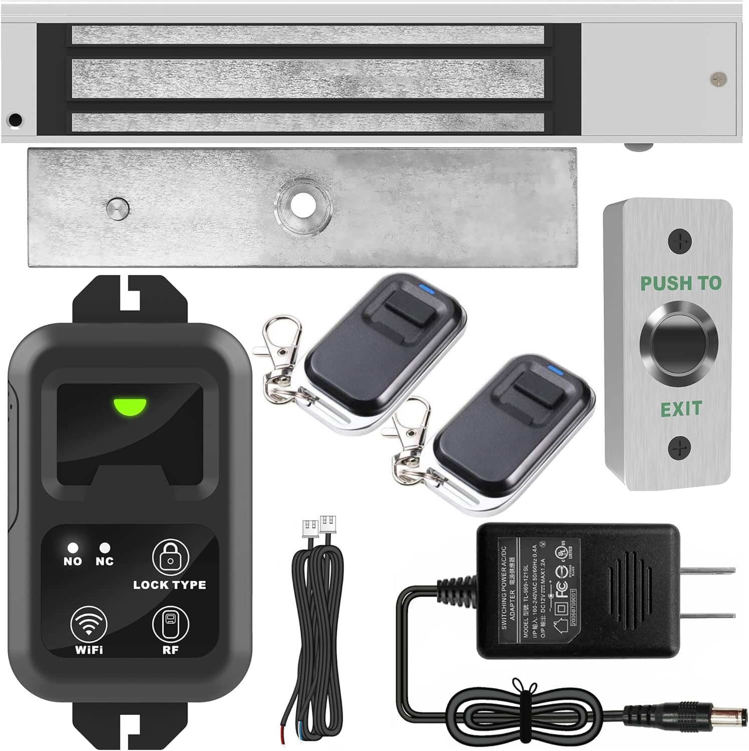
Figure 1: UHPPOTE 2.4GHz WiFi Access Control Remote Switch System with smartphone app interface.
2. Package Contents
Ensure all the following components are present in your package:
- Remote Control Unit (HBK-RW01)
- Electric Magnetic Lock (600lb)
- RF Remote Transmitters (2 included)
- Exit Button
- Power Adapter (12VDC)
- Mounting Hardware

Figure 2: Front view of the remote control unit (HBK-RW01).

Figure 3: Back view of the remote control unit, highlighting the buzzer, mode, and time delay switches.

Figure 4: The 600lb Electric Magnetic Lock component.

Figure 5: An RF Remote Control Transmitter.

Figure 6: The 12VDC Power Adapter.

Figure 7: The Push to Exit Button.
3. Installation and Wiring
Careful installation and correct wiring are crucial for the proper functioning of the access control system. Refer to the diagrams below for guidance.
3.1 System Diagram

Figure 8: An overview of the access control system components and their placement relative to a door.
3.2 Wiring Connections
Follow the wiring diagram carefully. Incorrect wiring can damage the device or prevent it from functioning.

Figure 9: Detailed wiring connections for the remote control unit, access keypad, exit button, and fail-secure/fail-safe locks.
Wiring Steps:
- Power Supply: Connect the 12VDC power adapter to the remote control unit's power port.
- Magnetic Lock: Connect the magnetic lock to the remote control unit's lock port. Ensure correct polarity (+12V to red wire, GND to black wire).
- Exit Button: Connect the exit button to the remote control unit's exit button port. Typically, the white wire connects to COM and the blue wire to NO (Normally Open) for a fail-secure setup.
- Access Keypad (Optional): If using an external access keypad, connect its PUSH and COM outputs to the corresponding PUSH and COM inputs on the remote control unit. Ensure the keypad's power is also connected to the 12VDC supply.
Video 1: A detailed demonstration of the wiring process for the HBK-RW01 remote control unit with various access components.
4. Operation
4.1 Smartphone App Control (Tuya Smart)
To control the system via your smartphone, download the Tuya Smart app from the App Store (iOS) or Google Play (Android).
- Register or log in to your Tuya Smart account.
- Ensure the remote control unit is powered on.
- In the app, tap the 'Add Device' button.
- On the remote control unit, tap and hold the WiFi icon for 8 seconds to enter pairing mode (the indicator light will blink).
- Follow the in-app instructions to connect to your 2.4GHz WiFi network and pair the device.
- Once paired, you can remotely control the lock (ON/OFF) and set timing functions.
4.2 RF Remote Pairing
To pair an RF remote transmitter with the remote control unit:
- On the remote control unit, tap the RF icon (Lock Type). The indicator light will turn red.
- Within 20 seconds, press any button on the RF remote transmitter you wish to pair.
- A successful pairing will be indicated by a sound from the buzzer and the indicator light turning green briefly.
4.3 RF Remote Unpairing
To unpair all RF remote transmitters from the remote control unit:
- On the remote control unit, tap and hold the RF icon for 8 seconds.
- The buzzer will sound, indicating that all paired transmitters have been cleared.
4.4 Lock Type Setting
The remote control unit supports two lock types: Fail-Safe (NC) and Fail-Secure (NO).
- Fail-Safe (NC): The lock will unlock during a power failure. To select, tap the Lock Type icon until the NC indicator lights up.
- Fail-Secure (NO): The lock will remain locked during a power failure. To select, tap the Lock Type icon until the NO indicator lights up.
4.5 Function Settings (DIP Switches)
The back of the remote control unit features DIP switches for advanced settings:
- Buzzer: Toggle ON/OFF to enable or disable sound effects for operations.
- Mode: Select between Latched, Toggle, or Momentary modes for lock operation.
- Time Delay: When in Momentary mode, set the time delay for the lock to 0, 5, or 10 seconds.

Figure 10: The remote control unit's front panel showing indicator lights and icons for Lock Type, WiFi, and RF pairing.
5. Specifications
| Feature | Specification |
|---|---|
| Brand | UHPPOTE |
| Model Number | UT-WIFI-280KG-814A |
| Color | Silver |
| Power Source | Corded Electric |
| Compatible Devices | Smartphone |
| Connectivity Technology | Wireless (2.4GHz WiFi) |
| Installation Type | Self-Adhesive |
| Item Weight | 3.3 pounds (1.5 Kilograms) |
| Voltage | 240 Volts (Input for adapter, output 12VDC) |
| Control Method | App, Remote |
| Maximum Range (RF) | 100 Feet |
| Included Components | Electromagnetic Lock, Remote Control, Transmitter, Exit Button, Power Adapter |
| Material | Metal, Plastic |
6. Maintenance
To ensure optimal performance and longevity of your UHPPOTE Access Control System, follow these maintenance guidelines:
- Regularly check all wiring connections for any signs of wear or damage. Ensure all connections are secure.
- Keep the remote control unit, magnetic lock, and exit button clean and free from dust and debris. Use a soft, dry cloth for cleaning.
- Test the system periodically to ensure the remote controls, app control, and exit button are functioning correctly.
- For the magnetic lock, ensure the armature plate and magnet surface are clean and free of obstructions for proper engagement.
- If using batteries in RF remote transmitters, replace them as needed to maintain reliable operation.
7. Troubleshooting
If you encounter issues with your access control system, refer to the following common troubleshooting steps:
- System Not Responding: Check if the power adapter is securely plugged in and providing power. Verify all wiring connections are correct and tight.
- RF Remote Not Working: Ensure the remote is paired correctly. Try re-pairing the remote as described in Section 4.2. Check the remote's battery.
- WiFi App Control Issues: Confirm your smartphone is connected to a 2.4GHz WiFi network. Ensure the remote control unit is in WiFi pairing mode (blinking indicator) when attempting to connect via the app. Check your WiFi password.
- Lock Not Engaging/Disengaging: Verify the lock type setting (Fail-Safe/Fail-Secure) is appropriate for your setup. Inspect the magnetic lock and armature plate for any physical obstructions or damage.
- Buzzer Not Sounding: Check the Buzzer DIP switch on the back of the remote control unit to ensure it is set to ON.
If problems persist after attempting these steps, please contact UHPPOTE customer support for further assistance.
8. Warranty and Support
UHPPOTE products are designed for reliability and performance. For warranty information and technical support, please refer to the documentation included with your purchase or visit the official UHPPOTE website. Keep your purchase receipt as proof of purchase for warranty claims.
Contact Information:
- Brand Store: Visit the UHPPOTE Store
- Manufacturer: UHPPOTE


