1. Introduction
The PAC VS41 Intelligent 4-Camera Switcher is designed to integrate up to four camera inputs with a vehicle's video display. This system enhances driver awareness by automatically activating cameras based on vehicle behavior, such as shifting into reverse or engaging turn signals. It also allows for manual camera selection via a remote control.
This manual provides detailed instructions for the proper installation, operation, and maintenance of your VS41 Intelligent 4-Camera Switcher.
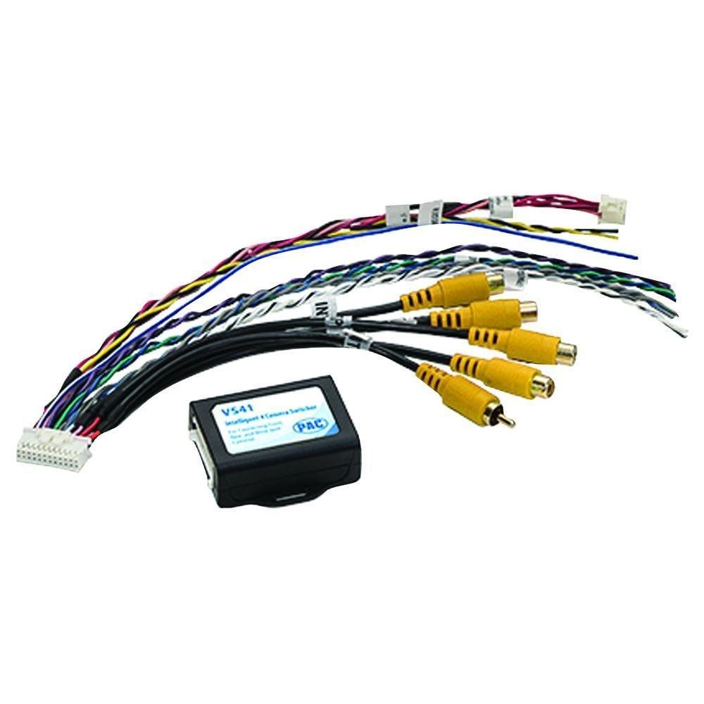
Figure 1.1: The PAC VS41 Intelligent 4-Camera Switcher unit.
2. Product Overview
The VS41 system includes the main switcher unit, a wiring harness with RCA connectors for camera inputs and video output, and a wireless remote control for manual camera selection.
2.1 Components
- VS41 Switcher Unit: The central processing unit for camera signal management.
- Wiring Harness: Connects power, ground, trigger inputs, camera inputs, and video output.
- Wireless Remote Control: For manual selection of camera views.

Figure 2.1: The VS41 Switcher unit with its integrated wiring harness.

Figure 2.2: Close-up view of the yellow RCA connectors for camera inputs.
3. Setup and Installation
Proper installation is crucial for the optimal performance of the VS41 switcher. It is recommended that installation be performed by a qualified professional.
3.1 Wiring Diagram
The VS41 features four camera inputs (Front, Left, Right, Rear) and one video output to connect to your vehicle's display. Trigger wires are used to automatically switch camera views.

Figure 3.1: Wiring diagram illustrating connections for power, video inputs, video output, and trigger lines.
3.2 Connection Steps
- Power Connection: Connect the 12V power cord to a switched 12V power source in your vehicle. Ensure a proper ground connection.
- Camera Inputs: Connect your front, left, right, and rear cameras to the corresponding RCA input jacks on the VS41 harness.
- Video Output: Connect the single video output RCA cable from the VS41 to the video input of your vehicle's display unit.
- Trigger Wires:
- Connect the Rear view trigger line to the vehicle's reverse light circuit. This will automatically activate the rear camera when the vehicle is in reverse.
- Connect the Left view trigger line to the vehicle's left turn signal circuit. This will activate the left camera when the left turn signal is engaged.
- Connect the Right view trigger line to the vehicle's right turn signal circuit. This will activate the right camera when the right turn signal is engaged.
- The Front view trigger line can be connected to a dedicated switch or integrated with other vehicle systems as desired.
- Remote Control Pairing: Follow the instructions provided with the remote control to pair it with the VS41 unit.
Important: Ensure all connections are secure and properly insulated to prevent short circuits or signal interference. Incorrect wiring can damage the unit or vehicle electronics.
4. Operating Instructions
The VS41 switcher operates both automatically via trigger inputs and manually using the wireless remote control.
4.1 Automatic Camera Activation
- Rear View: When the vehicle is shifted into reverse, the rear camera view will automatically display on your screen.
- Side Views: Engaging the left or right turn signal will automatically display the corresponding side camera view.
4.2 Manual Camera Selection (Wireless Remote)
The wireless remote control allows you to manually select camera views or exit the camera display.

Figure 4.1: Wireless remote control with labeled buttons for camera selection.
- F (Forward Looking Button): Press to display the front camera view.
- L (Left View Button): Press to display the left side camera view.
- R (Right Button): Press to display the right side camera view.
- B (Rear View Button): Press to display the rear camera view.
- M (Exit Button): Press to exit the camera display and return to the previous screen (e.g., radio, navigation).
Video 4.1: Demonstration of the Intelligent Car Video Switcher Converter in operation. This video illustrates the functionality and benefits of using a multi-camera system for enhanced driving safety and awareness.
5. Maintenance
The PAC VS41 Intelligent 4-Camera Switcher requires minimal maintenance to ensure long-term performance.
- Cleaning: Keep the switcher unit and remote control clean and free from dust and debris. Use a soft, dry cloth for cleaning. Avoid harsh chemicals or abrasive materials.
- Connections: Periodically check all wiring connections to ensure they remain secure. Loose connections can lead to intermittent signal loss or malfunction.
- Remote Battery: If the remote control becomes unresponsive, replace its battery. Refer to the remote control's specific instructions for battery replacement.
6. Troubleshooting
If you encounter issues with your VS41 switcher, refer to the following troubleshooting guide before seeking professional assistance.
| Problem | Possible Cause | Solution |
|---|---|---|
| No video signal on display. |
|
|
| Camera does not activate automatically. |
|
|
| Remote control is unresponsive. |
|
|
| Delayed switching between cameras. | This is normal for some trigger-based systems, typically 2-3 seconds. If excessive, check connections. | Ensure all connections are solid. If using an expansion port (if available on your specific vehicle interface), this delay may be reduced. |
7. Specifications
- Model Number: VS41
- Product Dimensions: 5.5 x 4 x 0.4 inches
- Item Weight: 3.2 ounces
- Inputs: 4 Camera Inputs (RCA)
- Output: 1 Video Output (RCA)
- Power Requirement: 12V DC
- Manufacturer: PAC Audio
8. Warranty and Support
For warranty information and technical support, please refer to the documentation provided with your purchase or visit the official PAC Audio website. Keep your proof of purchase for warranty claims.


