1. Introduction
This manual provides comprehensive instructions for the installation, operation, and maintenance of your Sommer Duo Vision 650 garage door motorization system. Please read this manual carefully before beginning installation or operation to ensure safe and efficient use of the product. Keep this manual for future reference.
The Sommer Duo Vision 650 is designed for automating various types of garage doors, offering convenience and enhanced security. It features a separate control unit, easy electrical installation, and advanced safety mechanisms like electronic force measurement and soft start/stop functions.
2. Safety Information
WARNING: Improper installation or use can lead to serious injury or death. Always follow these safety guidelines.
- Ensure all electrical connections are performed by a qualified electrician and comply with local regulations.
- Do not allow children to play with the garage door opener or its controls. Keep remote controls out of reach of children.
- Keep the garage door area clear of obstructions while the door is in motion.
- Regularly inspect the garage door system, including springs, cables, rollers, and other hardware, for signs of wear or damage. Do not attempt to repair these components yourself; contact a qualified service technician.
- Test the safety reverse system monthly. Place a 2x4 board flat on the floor in the path of the door. The door must reverse upon contact with the board. If it does not, adjust or repair the opener.
- In case of power failure, use the manual release mechanism to operate the door.
- Never stand or walk under a moving garage door.
3. Package Contents
Verify that all components listed below are present in your package:
- Sommer Duo Vision 650 Motor Unit
- Rail System (length may vary, typically for doors up to 2.6m high)
- Separate Control Unit with integrated push-button and lighting
- Handheld Transmitter 4020
- Mounting Hardware (screws, brackets, etc.)
- Instruction Manual

Image 3.1: Sommer Duo Vision 650 Motor Unit. This image shows the main motor unit of the garage door opener.
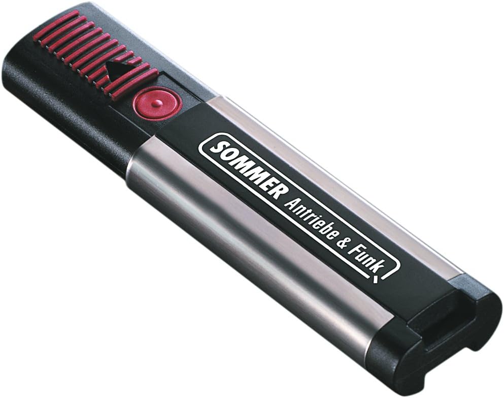
Image 3.2: Sommer Handheld Transmitter 4020. This is the remote control used to operate the garage door opener.

Image 3.3: Sommer Wall-Mounted Control Unit. This unit includes an integrated push-button and lighting for interior control.
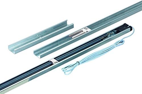
Image 3.4: Sommer Rail System Components. This image displays the various parts that make up the rail system for the garage door opener.
4. Setup and Installation
Before starting installation, ensure your garage door is in good working condition and properly balanced. Refer to the safety information in Section 2.
4.1. Overview of Installation Types

Image 4.1: Installation Examples. This image illustrates different mounting positions for the garage door opener: rear mounting, ceiling mounting, front mounting, and direct mounting on the track with a Duo mounting set.

Image 4.2: Component Diagram. This diagram shows the track unit, control unit, and ceiling mounting unit, highlighting their interconnections and features like the integral radio receiver and obstacle detection.
4.2. Rail Assembly
Assemble the rail sections according to the diagrams provided in the detailed installation guide (not included in this general manual, refer to the manufacturer's full guide for specific steps). Ensure all connections are secure. The rail is supplied with a travel length suitable for doors up to 2.6 meters high. Track extensions are available as accessories if needed.
4.3. Motor Unit and Control Unit Mounting
Mount the motor unit to the assembled rail. The separate control unit can be mounted on the wall or ceiling, offering flexibility. Use appropriate mounting hardware for your specific garage structure. The ceiling mounting unit provides flexibility and easy installation.

Image 4.3: Installed Garage Door Opener System. This image shows the Sommer Duo Vision 650 motorization system installed in a garage, with the rail and motor unit attached to the ceiling and the control unit mounted on the wall.
4.4. Electrical Connection
The system features easy electrical installation. No special ceiling outlet is required; it can be used with an existing standard outlet. Connect the motor unit to the control unit and then to a power source. Ensure all wiring is secure and protected. The control unit includes an integral radio receiver (FM 868.8 MHz) and 112 memory slots for transmitters.
4.5. Safety Feature Setup (DPS)
The Dynamic Power System (DPS) electronically measures the required force and adjusts to changing external conditions, ensuring high safety. During initial setup, the system will learn the door's travel limits and required force. Obstacle detection ensures the door reverses when meeting an obstacle. Test this feature as described in Section 2.
The system also features a controlled soft start and soft stop for smooth operation and reduced wear, contributing to its energy-efficient design.
5. Operating Instructions
5.1. Using the Handheld Transmitter (Remote Control)
The included Handheld Transmitter 4020 allows you to operate your garage door wirelessly. Press the designated button on the transmitter to open or close the garage door. Pressing it again during motion will stop the door. A third press will reverse the door's direction.
To program additional transmitters, refer to the detailed programming instructions in the full manufacturer's manual.
5.2. Using the Interior Push-Button
The separate control unit features an integrated push-button. Press this button to open or close the garage door from inside your garage. The integrated lighting will illuminate the garage when the door is operated.
5.3. Manual Release
In case of a power outage or malfunction, you can manually operate the garage door. Locate the manual release handle (usually a red cord) attached to the trolley on the rail. Pull the handle firmly to disengage the motor from the door. You can then open or close the door by hand. To re-engage, push the handle back into position or operate the opener once the power is restored.
6. Maintenance
Regular maintenance ensures the longevity and safe operation of your garage door motorization system.
- Monthly: Test the safety reverse system (refer to Section 2). Inspect the garage door for proper balance and smooth operation. Lubricate rollers, hinges, and bearings as recommended by your garage door manufacturer.
- Annually: Have a qualified technician inspect the entire garage door system, including springs, cables, and the opener.
- Keep the motor unit and control unit clean and free from dust and debris.
- Check the photocell sensors (if installed) for alignment and cleanliness.
Do not attempt to repair the motor unit or control unit yourself. Contact qualified service personnel for any repairs.
7. Troubleshooting
If your garage door opener is not functioning correctly, consult the following common issues and solutions:
| Problem | Possible Cause | Solution |
|---|---|---|
| Opener does not operate from remote or wall button. | No power; remote batteries dead; remote out of range; safety sensors obstructed. | Check power supply; replace remote batteries; ensure clear line of sight for remote; clear safety sensor path and align sensors. |
| Door reverses unexpectedly. | Obstruction in door path; safety sensors misaligned; force settings too high/low. | Remove obstruction; align safety sensors; adjust force settings (refer to full manual). |
| Door opens but does not close. | Safety sensors obstructed or misaligned. | Clear safety sensor path; align sensors. |
| Motor runs but door does not move. | Manual release engaged; broken spring or cable. | Re-engage manual release; contact a qualified technician for spring/cable repair. |
For more complex issues or if the problem persists, contact Sommer customer support or a certified service technician.
8. Specifications
| Brand | Sommer |
| Model | Duo Vision 650 |
| Part Number | 3010V000 |
| Traction and Pressure Force | 650 N |
| Max. Door Width (Swing Door) | 5000 mm |
| Max. Door Width (Sectional Door) | 5000 mm |
| Max. Door Width (Folding Gate) | 2800 mm |
| Max. Door Width (Side Section) | 2350 mm |
| Max. Door Height (Swing Door) | 2600 mm |
| Max. Door Height (Sectional Door) | 2350 mm |
| Max. Door Height (Folding Gate) | 2800 mm |
| Max. Door Height (Side Section) | 3000 mm |
| Max. Door Height (Up-and-Over Door) | 1900 mm |
| Color | Silver |
| Material | Metal |
| Assembly Required | Yes |
| Batteries Included | No (for main unit, remote batteries may be separate) |
| Batteries Required | No (for main unit, remote batteries may be separate) |
9. Warranty and Support
For warranty information, technical support, or to purchase replacement parts, please contact Sommer customer service directly. Refer to the manufacturer's official website or the packaging for specific contact details and warranty terms applicable to your region.
Always use genuine Sommer replacement parts to ensure proper function and maintain warranty validity.


