SENECA ZE-4DI-2AI-2DO Modbus TCP or IP Input or Output Module

PRELIMINARY WARNINGS
- The word WARNING preceded by the symbol indicates conditions or actions that put the user’s safety at risk. The word ATTENTION preceded by the symbol indicates conditions or actions that could damage the instrument or connected equipment.
- The warranty shall become null and void in the event of improper use or tampering with the module or devices supplied by the manufacturer as necessary for its correct operation, and if the instructions contained in this manual are not followed.
- WARNING: The full content of this manual must be read before any operation.
- The module must only be used by qualified electricians.
- Specific documentation is available using the QR-CODE shown on page 1.
- The module must be repaired and damaged parts replaced by the Manufacturer.
- The product is sensitive to electrostatic discharges. Take appropriate measures during any operation.
- Electrical and electronic waste disposal (applicable in the European Union and other countries with recycling).
- The symbol on the product or its packaging shows the product must be surrendered to a collection centre authorized to recycle
electrical and electronic waste.
FOR MORE INFO

CONTACT INFORMATION
- Technical support
- Product information
MODULE LAYOUT

- Single module dimensions LxHxD: 17.5 x 102.5 x 111 mm;
- Weight: 110 g;
- Enclosure: PA6, black
- Double module dimensions LxHxD: 35 x 102.5 x 111 mm;
- Weight: 110 g;
- Enclosure: PA6, black
LED SIGNALS ON THE FRONT PANEL (ZE-4DI-2AI-2DO / -P)
| LED STATUS MEANING | ||
| IP / PWR | ON | Module powered IP address acquired |
| IP / PWR | Flashing | Module powered waiting for IP address from the DHCP server / Profinet communication |
| Tx/Rx | Flashing | Data transmission and reception on at least one Modbus port |
| ETH TRF | Flashing | Packet transmission on Ethernet port |
| ETH LNK | ON | Ethernet port connected |
| DI1, DI2, DI3, DI4 | On / Off | Status of digital input 1, 2, 3, 4 |
| DO1, DO2 | On / Off | Status of output 1, 2 |
| FAIL | Flashing | Outputs in fail condition |
LED SIGNALS ON THE FRONT PANEL (Z-4DI-2AI-2DO)
| LED | STATUS | MEANING |
| PWR | ON | Module powered |
| Tx/Rx | Flashing | Data transmission and reception on at least one Modbus port: COM1, COM2 |
| DI1, DI2, DI3, DI4 | On / Off | Status of digital input 1, 2, 3, 4 |
| DO1, DO2 | On / Off | Status of output 1, 2 |
| FAIL | Flashing | Outputs in fail condition |
LED SIGNALS ON THE FRONT PANEL (ZE-2AI / -P)
| LED STATUS MEANING | ||
| IP / PWR | ON | Module powered and IP address acquired |
| IP / PWR | Flashing | Module powered waiting for IP address from the DHCP server / Profinet communication |
| FAIL | ON | At least one of the two analogue inputs is out of scale (underscale-overscale) |
| ETH TRF | Flashing | Packet transmission on Ethernet port |
| ETH LNK | ON | Ethernet port connected |
| Tx1 | Flashing | Modbus packet transmission from device to COM 1 port |
| Rx1 | Flashing | Modbus packet reception on COM 1 port |
| Tx2 | Flashing | Modbus packet transmission from device to COM 2 port |
| Rx2 | Flashing | Modbus packet reception on COM 2 port |
TECHNICAL SPECIFICATIONS


INSTALLATION REGULATIONS
The module has been designed for vertical installation on a DIN 46277 rail. For optimal operation and long life, adequate ventilation must be provided. Avoid positioning ducting or other objects that obstruct the ventilation slots. Avoid mounting modules over heat-generating equipment. Installation in the bottom part of the electrical panel is recommended.
CAUTION
These are open type devices intended for installation in a final casing/panel that offers mechanical protection and protection against the spread of fire.
ModBUS CONNECTION RULES
- Install the modules in the DIN rail (120 max)
- Connect the remote modules using cables of an appropriate length. The following table shows cable length data:
- Bus length: maximum length of the Modbus network according to the Baud Rate. This is the length of the cables that connect the two farthest modules (see Diagram 1).
- Derivation length: maximum length of a derivation 2 m (see Diagram 1).

For maximum performance, it is recommended to use special shielded cables, designed specifically for data communication.
IDC10 CONNECTOR
Power supply and Modbus interface are available using the Seneca DIN rail bus, via the IDC10 rear connector, or the Z-PCDINAL-17.5 accessory.

Back connector (IDC 10)
The illustration shows the meanings of the various IDC10 connector pins if signals are to be sent via them directly.
USB PORT (Z-4DI-2AI-2DO)
The module is designed to exchange data according to the modes defined by the MODBUS protocol. It has a micro USB connector and can be configured using applications and/or software programs. The USB serial port uses the following communication parameters: 115200,8,N,1
The USB communication port behaves exactly like that of the RS485 or RS232 bus except for the communication parameters.

SETTING THE DIP-SWITCHES
WARNING
The DIP-switch settings are read only at boot time. At each change, perform a restart.
SW1 DIP-SWITCH:
Through DIP-SWITCH-SW1 it is possible to set the IP configuration of the device:

CAUTIO
- Where present, DIP3 and DIP4 must be set to OFF.
- If set differently, the instrument will not work correctly
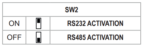
RS232/RS485 SETTING:
RS232 or RS485 setting on terminals 10 -11 -12 (serial port 2)
WEB SERVER
- To access the maintenance Web Server with the factory IP address 192.168.90.101 enter: http://192.168.90.101
- Default user: admin, Default password: admin.
CAUTION
DO NOT USE DEVICES WITH THE SAME IP ADDRESS IN THE SAME ETHERNET NETWORK.
ELECTRICAL CONNECTIONS
Attention: the upper power supply limits must not be exceeded, as this might cause serious damage to the module.
To meet the electromagnetic immunity requirements:
- use shielded signal cables;
- connect the shield to a preferential instrumentation earth system;
- separate shielded cables from other cables used for power installations (transformers, inverters, motors, induction ovens, etc…).
POWER SUPPLY
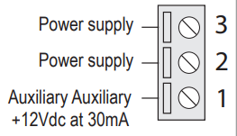
- The power supply is connected to terminals 2 and 3.
- The supply voltage must be between:
11 and 40Vdc (indifferent polarity), or between 19 and 28 Vac. - The power supply source must be protected from the malfunctions of the module through an appropriately-sized safety fuse.
ANALOGUE INPUTS

DIGITAL INPUTS (ONLY ZE-4DI-2AI-2DO and Z-4DI-2AI-2DO)

DIGITAL OUTPUTS (ONLY ZE-4DI-2AI-2DO and Z4DI-2AI-2DO)

COM2 SERIAL PORT

Documents / Resources
 |
SENECA ZE-4DI-2AI-2DO Modbus TCP or IP Input or Output Module [pdf] Instruction Manual ZE-4DI-2AI-2DO, ZE-4DI-2AI-2DO-P, Z-4DI-2AI-2DO, ZE-2AI, ZE-2AI-P, ZE-4DI-2AI-2DO Modbus TCP or IP Input or Output Module, Modbus TCP or IP Input or Output Module, TCP or IP Input or Output Module, IP Input or Output Module, Input or Output Module, Module |


