Reolink CDW-B18188F-QA WLAN 11 b g n USB Module
 CDW-B18188F-QA
DATASHEET
Software:
| Customer | Approve) | Date |
| Design | Check | Approve | Version | Date |
| V1.3 | 2021.11.03 |
Overview
CDW-B18188F-QA is a WLAN 11 b/g/n USB module, which fully supports the features and Functional compliance of IEEE 802.11 b/g/n standards. It supports up to 72.2Mbps high-speed wireless network connections. It is designed to provide excellent performance with low power Consumption and enhance the advantages of robust system and cost-effective. It is targeted at competitive superior performance, better power Management applications.
Features
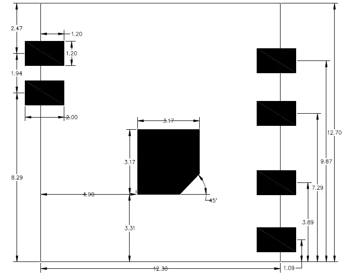
- 6 -pin ,Total Size 12.7×12.3×1.6mm
- single chip for IEEE 802.11b/g/n compatible WLAN
- Complete 802.11n solution for 2.4GHz band
- 72.2Mbps receive PHY rate and 72.2Mbps transmit PHY rate using 20MHz bandwidth
- Compatible with 802.11n specification
- Backward compatible with 802.11b/g devices while operating in 802.11n mode Interface
- Complies with USB 1.0/1.1/2.0 for WLAN Standards Supported
- IEEE 802.11b/g/n compatible WLAN
- IEEE 802.11e QoS Enhancement (WMM)
- 802.11i (WPA, WPA2). Open, shared key, and pair-wise key authentication services
General Specification
| Model | CDW-B18188F-QA |
| Product Name | WLAN 11n USB 2.0 module |
| Major Chipset | RTL8188F-VQ1 |
| Standard | 802.11b/g/n |
| Modulation Method | BPSK/ QPSK/ 16-QAM/ 64-QAM |
| PCBA Dimension | 12.7×12.2×1.6(L×W×H)+-0.15mm |
| Frequency Band | 2412-2472MHz for 802.11b/g/n20BW |
| Channels | 802.11b/g/n-20MHz:13 |
| Test Tone deviation | +/-75kHz |
| Security | WEP, TKIP, AES, WPA, WPA2 |
| Interface | USB 2.0 |
| Voltage | 3.3V |
| Operating Temperature | -20~ +60° C |
| Storage Temperature | -20 ~+70°C |
| Humidity | 5 to 90 % maximum (non-condensing) |
Electrical Characteristics
| Feature | Description | |||
| WLAN Standard | IEEE 802.11b/g/n WiFi compliant | |||
| Frequency Range | 2.400 GHz ~ 2.497 GHz (2.4 GHz ISM Band) | |||
| Number of Channels | 2.4GHz:Ch1 ~ Ch13 | |||
| Modulation | 802.11b : DQPSK, DBPSK, CCK802.11 g/n : OFDM /64-QAM,16-QAM, QPSK, BPSK | |||
| Output Power | 802.11b /11Mbps : 17dBm ± 2 dB @ EVM ≤ -15dB | |||
| 802.11g /54Mbps : 14.5 dBm ± 2 dB @ EVM ≤ -25dB | ||||
| 802.11n /MCS7: 13.5 dBm ± 2 dB @ EVM ≤ -28dB | ||||
| RX sensitivity | Mode | Data Rate | Sensitivity(Type) | Unit |
| 11b | 11Mbps | -85 | dBm | |
| 11g | 54Mbps | -72 | dBm | |
| 11n HT20 | MCS7 | -70 | dBm | |
DC Characteristics
| Description | TYP | Unit |
| Sleep mode | 5 | mA |
| RX Active,HT20,MCS7 | 145 | mA |
| TX HT20,mcs7 @14dBm | 190 | mA |
| TX CCK,11Mbps @19dBm | 310 | mA |
Note: All result is measured at the antenna port and VDD33 is 3.3V
Pin Description and PCB size
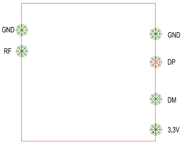
| NO. | Symbol | Description |
| 1 | VCC | Power supply 3.3V is required |
| 2 | DM | USB negative differential data lines |
| 3 | DP | USB positive differential data lines |
| 4 | GND | Ground connections |
| 5 | GND | Ground connections |
| 6 | RF | RF out External PI-type circuit is requested |
PCB size
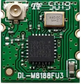
Modular photo
| Crystal | 40Mhz | ,MDH |
| PCBA VER | B18188F |
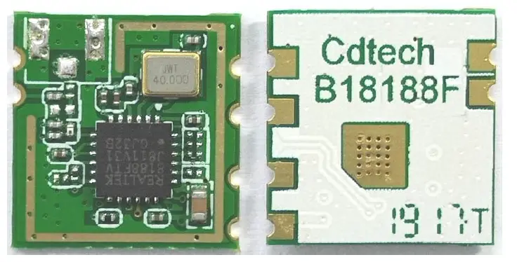
PCBA physical photo
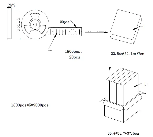
Package
 ESD CAUTION
The CDW-B18188F-QA is ESD (electrostatic discharge) sensitive device and may be damaged with ESD or spike voltage. Although CDW-B18188F-QA is with built-in ESD protection circuitry, please handle with care to avoid the permanent malfunction or the performance degradation.
Requirement per KDB996369 D03
List of applicable FCC rules
List the FCC rules that are applicable to the modular transmitter. These are the rules that specifically establish the bands of operation, the power, spurious emissions, and operating fundamental frequencies. DO NOT list compliance to unintentional-radiator rules (Part 15 Subpart B) since that is not a condition of a module grant that is extended to a host manufacturer. See also Section 2.10 below concerning the need to notify host manufacturers that further testing is required.3
Explanation: This module meets the requirements of FCC part 15C(15.247).
Summarize the specific operational use conditions
Describe use conditions that are applicable to the modular transmitter, including for example any limits on antennas, etc. For example, if point-to-point antennas are used that require reduction in power or compensation for cable loss, then this information must be in the instructions. If the use condition limitations extend to professional users, then instructions must state that this information also extends to the host manufacturer’s instruction manual. In addition, certain information may also be needed, such as peak gain per frequency band and minimum gain, specifically for master devices in 5 GHz DFS bands.
Explanation: The EUT has a FPC Antenna, and the antenna use a permanently attached antenna which is not replaceable.
Limited module procedures
If a modular transmitter is approved as a “limited module,” then the module manufacturer is responsible for approving the host environment that the limited module is used with. The manufacturer of a limited module must describe, both in the filing and in the installation instructions, the alternative means that the limited module manufacturer uses to verify that the host meets the necessary requirements to satisfy the module limiting conditions.
A limited module manufacturer has the flexibility to define its alternative method to address the conditions that limit the initial approval, such as: shielding, minimum signaling amplitude, buffered modulation/data inputs, or power supply regulation. The alternative method could include that the limited module manufacturer reviews detailed test data or host designs prior to giving the host manufacturer approval. This limited module procedure is also applicable for RF exposure evaluation when it is necessary to demonstrate compliance in a specific host. The module manufacturer must state how control of the product into which the modular transmitter will be installed will be maintained such that full compliance of the product is always ensured. For additional hosts other than the specific host originally granted with a limited module, a Class II permissive change is required on the module grant to register the additional host as a specific host also approved with the module.
Explanation: The module is not a limited module.
Trace antenna designs
For a modular transmitter with trace antenna designs, see the guidance in Question 11 of KDB Publication 996369 D02 FAQ – Modules for Micro-Strip Antennas and traces. The integration information shall include for the TCB review the integration instructions for the following aspects: layout of trace design, parts list (BOM), antenna, connectors, and isolation requirements.
- Information that includes permitted variances (e.g., trace boundary limits, thickness, length, width, shape(s), dielectric constant, and impedance as applicable for each type of antenna);
- Each design shall be considered a different type (e.g., antenna length in multiple(s) of frequency, the wavelength, and antenna shape (traces in phase) can affect antenna gain and must be considered);
- The parameters shall be provided in a manner permitting host manufacturers to design the printed circuit (PC) board layout;
- Appropriate parts by manufacturer and specifications;
- Test procedures for design verification; and
- Production test procedures for ensuring compliance.
The module grantee shall provide a notice that any deviation(s) from the defined parameters of the antenna trace, as described by the instructions, require that the host product manufacturer must notify the module grantee that they wish to change the antenna trace design. In this case, a Class II permissive change application is required to be filed by the grantee, or the host manufacturer can take responsibility through the change in FCC ID (new application) procedure followed by a Class II permissive change application.
Explanation: Yes, The module with trace antenna designs, and This manual has been shown the layout of trace design, antenna, connectors, and isolation requirements.
RF exposure considerations
It is essential for module grantees to clearly and explicitly state the RF exposure conditions that permit a host product manufacturer to use the module. Two types of instructions are required for RF exposure information:(1) to the host product manufacturer, to define the application conditions (mobile, portable – xx cm from a person’s body); and (2) additional text needed for the host product manufacturer to provide to end users in their end-product manuals. If RF exposure statements and use conditions are not provided, then the host product manufacturer is required to take responsibility of the module through a change in FCC ID (new application).
Explanation: This module complies with FCC RF radiation exposure limits set forth for an uncontrolled environment, This equipment should be installed and operated with a minimum distance of 20 centimeters between the radiator and your body.” This module is designed to comply with the FCC statement, FCC ID is: 2AYHE-2406B
Antennas
A list of antennas included in the application for certification must be provided in the instructions. For modular transmitters approved as limited modules, all applicable professional installer instructions must be included as part of the information to the host product manufacturer. The antenna list shall also identify the antenna types (monopole, PIFA, dipole, etc. (note that for example an “omni-directional antenna” is not considered to be a specific “antenna type”)).
For situations where the host product manufacturer is responsible for an external connector, for example with an RF pin and antenna trace design, the integration instructions shall inform the installer that unique antenna connector must be used on the Part 15 authorized transmitters used in the host product. The module manufacturers shall provide a list of acceptable unique connectors.
Explanation: The EUT has FPC Antenna, and the antenna use a permanently attached antenna which is unique.
Label and compliance information
Grantees are responsible for the continued compliance of their modules to the FCC rules. This includes advising host product manufacturers that they need to provide a physical or e-label stating “Contains FCC ID” with their finished product. See Guidelines for Labeling and User Information for RF Devices – KDB Publication 784748.
Explanation: The host system using this module, should have label in a visible area indicated the following texts: “Contains FCC ID: 2AYHE-2406B, Contains IC: 26839-2406B”
Information on test modes and additional testing requirements5
Additional guidance for testing host products is given in KDB Publication 996369 D04 Module Integration Guide. Test modes should take into consideration different operational conditions for a stand-alone modular transmitter in a host, as well as for multiple simultaneously transmitting modules or other transmitters in a host product. The grantee should provide information on how to configure test modes for host product evaluation for different operational conditions for a stand-alone modular transmitter in a host, versus with multiple, simultaneously transmitting modules or other transmitters in a host.
Grantees can increase the utility of their modular transmitters by providing special means, modes, or instructions that simulates or characterizes a connection by enabling a transmitter. This can greatly simplify a host manufacturer’s determination that a module as installed in a host complies with FCC requirements.
Explanation: Top band can increase the utility of our modular transmitters by providing instructions that simulates or characterizes a connection by enabling a transmitter.
Additional testing, Part 15 Subpart B disclaimer
The grantee should include a statement that the modular transmitter is only FCC authorized for the specific rule parts (i.e., FCC transmitter rules) listed on the grant, and that the host product manufacturer is responsible for compliance to any other FCC rules that apply to the host not covered by the modular transmitter grant of certification. If the grantee markets their product as being Part 15 Subpart B compliant (when it also contains unintentional-radiator digital circuity), then the grantee shall provide a notice stating that the final host product still requires Part 15 Subpart B compliance testing with the modular transmitter installed.
Explanation: The module without unintentional-radiator digital circuity, so the module does not require an evaluation by FCC Part 15 Subpart B. The host shoulde be evaluated by the FCC Subpart B.
FCC STATEMENT
This device complies with Part 15 of the FCC Rules. Operation is subject to the following two conditions:
- This device may not cause harmful interference, and
- This device must accept any interference received, including interference that may cause undesired operation.
Warning: Changes or modifications not expressly approved by the party responsible for compliance could void the user’s authority to operate the equipment.
NOTE: This equipment has been tested and found to comply with the limits for a Class B digital device, pursuant to Part 15 of the FCC Rules. These limits are designed to provide reasonable protection against harmful interference in a residential installation. This equipment generates uses and can radiate radio frequency energy and, if not installed and used in accordance with the instructions, may cause harmful interference to radio communications. However, there is no guarantee that interference will not occur in a particular installation. If this equipment does cause harmful interference to radio or television reception, which can be determined by turning the equipment off and on, the user is encouraged to try to correct the interference by one or more of the following measures:
- Reorient or relocate the receiving antenna.
- Increase the separation between the equipment and receiver.
- Connect the equipment into an outlet on a circuit different from that to which the receiver is connected.
- Consult the dealer or an experienced radio/TV technician for help.
FCC Radiation Exposure Statement:
This equipment complies with FCC radiation exposure limits set forth for an uncontrolled environment. This equipment should be installed and operated with minimum distance 20cm between the radiator & your body.
ISED Statement
This device complies with Industry Canada licence-exempt RSS standard(s). Operation is subject to the following two conditions:
This equipment should be installed and operated with a minumum distance of 20 cm between the radiator and your body.
MODIFICATION: Any changes or modifications not expressly approved by the grantee of this device could void the user’s authority to operate the device.
This Class B digital apparatus complies with Canadian ICES-003. The OEM must certify the final end product to comply with unintentional radiators (FCC Sections 15.107 and 15.109) before declaring compliance of the final product to Part 15 of the FCC rules and regulations. Integration into devices that are directly or indirectly connected to AC lines must add with Class II Permissive Change. The OEM must comply with the FCC labeling requirements. If the module’s label is not visible when installed, then an additional permanent label must be applied on the outside of the finished product which states: “Contains transmitter module FCC ID: 2AYHE-2406B”. Additionally, the following statement should be included on the label and in the final product’s user manual: “This device complies with Part 15 of the FCC Rules. Operation is subject to the following two conditions:
The module is limited to installation in mobile or fixed applications. Separate approval is required for all other operating configurations, including portable configuration with respect to Part 2.1093 and different antenna configurations.
A module or modules can only be used without additional authorizations if they have been tested and granted under the same intended end‐use operational conditions, including simultaneous transmission operations. When they have not been tested and granted in this manner, additional testing and/or FCC application filing may be required. The most straightforward approach to address additional testing conditions is to have the grantee responsible for the certification of at least one of the modules submit a permissive change application.
When having a module grantee file a permissive change is not practical or feasible, the following guidance provides some additional options for host manufacturers. Integrations using modules where additional testing and/or FCC application filing(s) may be required are: (A) a module used in devices requiring additional RF exposure compliance information (e.g., MPE evaluation or SAR testing); (B) limited and/or split modules not meeting all of the module requirements; and (C) simultaneous transmissions for independent collocated transmitters not previously granted together.
This Module is full modular approval, it is limited to OEM installation ONLY. Integration into devices that are directly or indirectly connected to AC lines must add with Class II Permissive Change. (OEM) Integrator has to assure compliance of the entire end product include the integrated Module. Additional measurements (15B) and/or equipment authorizations (e.g. Verification) may need to be addressed depending on co-location or simultaneous transmission issues if applicable. (OEM) Integrator is reminded to assure that these installation instructions will not be made available to the end user
IC labeling requirement for the final end product:
The final end product must be labeled in a visible area with the following “Contains IC: 26839-2406B” The Host Marketing Name (HMN) must be indicated at any location on the exterior of the host product or product packaging or product literature, which shall be available with the host product or online.
This radio transmitter [ lC:26839-2406B] has been approved by Innovation, Science and Economic Development Canada to operate with the antenna types listed below, with the maximum permissible gain indicated. Antenna types not included in this list that have a gain greater than the maximum gain indicated for any type listed are strictly prohibited for use with this device.
| Frequency range | Manufacturer | Peak gain | Impedance | Antenna type |
| 2412~2462MHz | Shenzhen Be- Comfortable Technology Co. Ltd | 4.95dBi | 50Ω | FPC Antenna |
FAQ
Q: Is the CDW-B18188F-QA module ESD sensitive?
A: Yes, the CDW-B18188F-QA is an ESD sensitive device. Handle with care to avoid permanent malfunction or performance degradation.
Documents / Resources
 |
Reolink CDW-B18188F-QA WLAN 11 b g n USB Module [pdf] Owner's Manual 2406B, 2AYHE-2406B, 2AYHE2406B, CDW-B18188F-QA WLAN 11 b g n USB Module, CDW-B18188F-QA, WLAN 11 b g n USB Module, USB Module, Module |