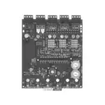
NOTIFIER FZM-1A Interface Module

Specifications
- Normal Operating Voltage: 15 to 32 VDC
- Maximum Current Draw: 5.1 mA (LED on)
- Average Operating Current: EOL Resistance: 3.9K Ohms
- Maximum IDC Wiring Resistance: 25 Ohms IDC Supply Voltage (between Terminals T10 and T11)
- Regulated DC Voltage: 24 VDC power limited
- Ripple Voltage: 0.1 Volts RMS maximum
- Alarm Current: 90 mA per module
- Standby Current: 13 mA Maximum @24 VDC
- Temperature Range
- Humidity: 10% to 93% Non-condensing
- Dimensions
- Accessories: SMB500 Electrical Box
INSTALLATION AND MAINTENANCE INSTRUCTIONS
FZM-1A Interface Module
SPECIFICATIONS
- Normal Operating Voltage: 15 to 32 VDC
- Maximum Current Draw: 5.1 mA (LED on)
- Average Operating Current: 270 μA (LED flashing)
- EOL Resistance: 3.9K Ohms
- Maximum IDC Wiring Resistance: 25 Ohms
- IDC Supply Voltage (between Terminals T10 and T11)
- Regulated DC Voltage: 24 VDC power limited
- Ripple Voltage: 0.1 Volts RMS maximum
- Alarm Current: 90 mA per module
- Standby Current: 13 mA Maximum @24 VDC
- Temperature Range: 32˚F to 120˚F (0˚C to 49˚C)
- Humidity: 10% to 93% Non-condensing
- Dimensions: 4.5˝ H × 4˝ W × 1.25˝ D (Mounts to a 4˝ square by 2.125˝ deep box.)
- Accessories: SMB500 Electrical Box
BEFORE INSTALLING
- This information is included as a quick reference installation guide. Refer to the control panel installation manual for detailed system information. If the modules will be installed in an existing operational system, inform the opera-tor and local authority that the system will be temporarily out of service. Dis-connect power to the control panel before installing the modules.
NOTICE: This manual should be left with the owner/user of this equipment.
GENERAL DESCRIPTION
- The FZM-1A Interface Module is intended for use in intelligent, two-wire systems, where the individual address of each module is selected using the built-in rotary switches. This module allows intelligent panels to interface and monitor two-wire conventional smoke detectors. It transmits the status (normal, open, or alarm) of one full zone of conventional detectors back to the control panel. All two-wire detectors being monitored must be ULC compatible with this module. The FZM-1A has a panel controlled LED indicator. FZM-1A is capable of handling more than one detector in alarm condition.
COMPATIBILITY REQUIREMENTS
To ensure proper operation, this module shall be connected to a compatible Notifies system control panel only (list available from Notified).
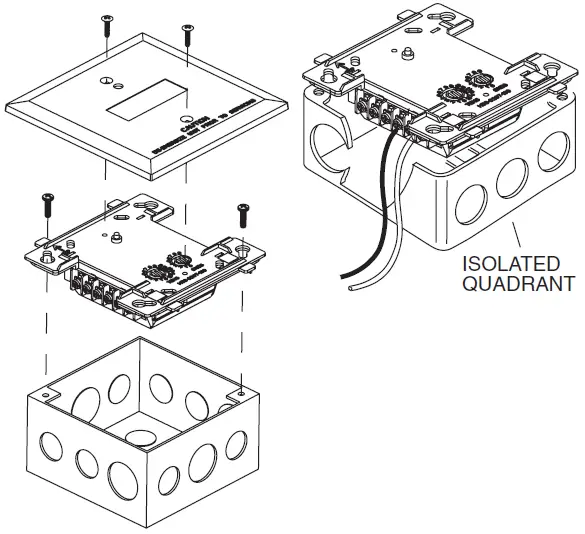
MOUNTING
- The FZM-1A mounts directly to 4-inch square electrical boxes. (See Figure 2.) The box must have a minimum depth of 2.125 inches. Surface mounted electrical boxes (SMB500) are available from Notified.
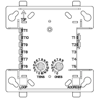
- FIGURE 1. CONTROLS AND INDICATORS
WIRING
NOTE: All wiring must conform to applicable local codes, ordinances, and regulations. This module is intended for power-limited wiring only.- Install module wiring in accordance with the job drawings and appropriate wiring diagrams.
- Set the address on the module per job drawings.
- Secure module to electrical box supplied by installer. (See Figure 2.)
- FIGURE 2. MODULE MOUNTING
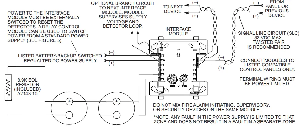
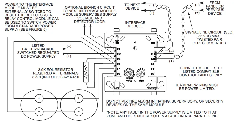
- FIGURE 3. INTERFACE TWO-WIRE CONVENTIONAL DETECTORS, NFPA CLASS B
- FIGURE 4. INTERFACE TWO-WIRE CONVENTIONAL DETECTORS, NFPA CLASS A
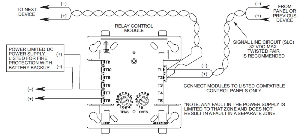
- FIGURE 5. RELAY CONTROL MODULE USED TO DISCONNECT A POWER SUPPLY
Documents / Resources
 |
NOTIFIER FZM-1A Interface Module [pdf] Installation Guide FZM-1A, FZM-1A Interface Module, Interface Module, Module |