![]()

![]() MWT-3100 – Leeb Hardness Tester
MWT-3100 – Leeb Hardness Tester
Operating Instructions
Brief Introduction
1.1 Features
- This hardness tester uses the proven Leeb rebound method to determine material hardness for a variety of metals
- High performance ARM processor for instantaneous measurement.
- The measured hardness value is shown above a table of equivalent values from other hardness standards with no need to look up a table or switch between screens.
- The device is able to monitor the effectiveness of each test and identify any detrimental factors such as probe wear or contamination within the probe casing.
- Powered by 2 AA size batteries with automatic shutdown and other power saving functions
- Size: 152mm × 77mm × 36mm
- Weight: 300g
1.2 Technical Characteristics
- See the table below for indication error and indication repeatability
Table 1-1
| No | Impact Device | Standard Hardness Test Block | Indication Error | Indication Repeatability |
| 1 | D (Standard) |
760±30HLD 530±40HLD |
±6 HLD ±10 HLD |
6 HLD 10 HLD |
- Measurement Range: 170 – 960 HLD
- Measuremeny supported in all directions including vertically up and down, horizontally and oblique angles.
- Measuring Materials: steel and cast steel, alloy tool steel, cast aluminum alloy, gray cast iron, nodular cast iron, stainless steel, copper zinc alloy (brass), copper tin alloy (bronze), pure copper.
- Equivalent Hardness Standards: Richter (HL), Brinell (HB), Rockwell B (HRB), Rockwell C (HRC), Vickers (HV), shore (HS).
- Up to 100 groups of data can be stored.
- Working Voltage: 3V (2x AA size alkaline batteries).
- Continuous Working Time: Low brightness – 15 hours. High brightness – 7 hours.
1.3 Standard Delivery
Table 1-2
| No. | Items | Qty. |
| 1 | Main unit | 1 |
| 2 | D impact device | 1 |
| 3 | Standard Test block | 1 |
| 4 | Brush | 1 |
| 5 | Supporting ring | 1 |
| 6 | AA battery | 1 |
| 7 | ABS suitcase | 1 |
1.4 Working Conditions
- Operating temperature: – 10 ˚C – +50˚C
- Storage Temperature: – 30˚C – +60˚C
- Relative Humidity ≤ 90%
- The device should never be used in environments with strong vibrations, strong magnetic fields, corrosive material or excessive dust.
Structural Features and Working Principle
2.1 Structural Features
Device Components
| 1 | Impact device socket |
| 2 | Impact device |
| 3 | Main unit |
| 4 | Keyboard |
| 5 | Screen |
2.1.1 Impact Device
Impact Device Components
| 1 | Release button |
| 2 | Loading sleeve |
| 3 | Guide tube |
| 4 | Coil |
| 5 | Cable |
| 6 | Impact body |
| 7 | Support ring |
2.2 Main Display Interface
On startup, the device will open to the main display, as shown below. Description
| Time | The current time, this can be changed in settings |
| Automatic Storage Icon | This icon appears when automatic storage mode is turned on |
| Battery Level | The charge of the battery |
| Measured Value | The measured value of the most recent test, or the current average value if the AVE flag is displayed. The display Hi Indicates that the conversion or measurement range is exceeded, and Lo Indicates that it is lower than the conversion or measurement range |
| Number of Measurements | The number of completed measurements are displayed here during measurement. Press the CNT key to set the required number of measurements |
| Average Icon | After reaching the required number of measurements, the average value icon will appear |
| Hardness Unit | The hardness unit for the current measured value |
| Equivalent Hardness values | The equivalent values of the test result in 6 other hardness units |
| Test Material | The material being tested |
| Impact Device Type | The type of impact device currently connected |
| Impact Direction | The current impact direction of the probe |
2.3 Keypad Details
| Material selection | |
| UP/Hardness system selection | |
| Enter the menu | |
| Direction / Left | |
| Data stastics / Down | |
| Save / Right | |
| Waveform view | |
| Average times setting | |
| On/Off |
- Press the
 key to change the material setting, each press will cycle through the materials.
 - The hardness unit can be changed by pressing the
 key. Each press will cycle through the equivalent hardness systems.
 - Press the
 key to enter the menu for various settings.
 - Press the
 key to modify the number of impacts required, press to display the current numbers of impact times, press or
  to adjust this number, and then exit.
 - Press the
 key to change the impact direction of the probe, each press will cycle through the available directions.
 - Press the
 key to save the measurement data without using automatic data saving. Data can only be saved as the display average value.
 - Press the key to view the table of statistical data for the measured results.
- Press the
 key to view the impact waveform generated during measurement. Refer to Section 2.4 for more on this working principle.
 - Press and hold
 for 3 seconds to start the device or to shut down.
2.4 Working Principle
A projectile is driven by elastic force to impact a surface at a known speed, this impact is used to calculate the test material’s hardness using the ratio of the rebound speed and the impact speed 1mm from the surface. The formula for this is:
HL=1000 × B/A
Where:
HL = Leeb hardness value
B = rebound speed of impact body
A = impact speed of impact body
The output signal diagram of the impact device is shown in the right figure:
Preparation Before Measurement
3.1 Instrument Preparation
Before using the instrument for the first time or after a long period without use, the device must be calibrated with a standard Leeb hardness block.
Press and hold the ![]() keys to enter the calibration window, as shown in the figure below:
keys to enter the calibration window, as shown in the figure below: Measure 5 points vertically downward on the calibrated Leeb hardness block. After measuring 5 points, the display will show the average value and AVE sign.
Press the ![]() keys to enter the known standard value.
keys to enter the known standard value.
Press OK to complete the calibration or press the return key to cancel.
3.2 Work Piece Requirements
The work piece must meet the requirements in Table A-2 and A-3. in the appendix and the following list:
- The surface temperature must not be greater than 120˚C
- The surface must not be rough otherwise this may cause measurement errors. The surface must be flat, smooth and free of oil or debris.
- For test pieces with a weight of 2-5kg, parts with an overhanging feature or those with thin walls, the test piece must be supported by another object during the test to avoid deformation, bending or movement caused by the impact force. Medium-sized working pieces must be placed on a flat and solid surface.
- The test surface should ideally be flat. When the radius R of the measured surface is less than 30mm a small support ring or should be used during the test.

- The workpiece thickness must be greater than 5mm.
- For workpieces with a surface hardening layer, this must be greater than 0.8mm
Measurement Method
Measure the hardness of the sample hardness block vertically downward 5 times with a calibrated Leeb hardness tester, take the mean value as the hardness. If this is different then the recalibrate the device.
Before taking a measurement, test the device with a known hardness block, the error and repeatability must not be greater than the values specified in Table 4-1.
4.1 Startup
- Plug the impact device into the instrument.
- Long press the key. The device will power on and enter the measurement state.
4.2 Loading
- Push down the sleeve to ‘load’ the probe and prepare for testing.
4.3 Positioning
Hold the base of the probe against the test surface, the impact direction must be perpendicular to the surface of the part. The sample and impact device must both stable for all measurements.
4.4 Measurement
- Press the release button at the top of the impact device to take a measurement. Each time a measurement is completed, the screen will display the measured value and the number ofimpacts increases by 1. If the measurement range is exceeded, the buzzer will make one long sound. After completing the set number of impacts, the buzzer will give two short beeps. After 2 seconds, the buzzer will give one short beep and display the average value.
- All measurements taken on the same part should not exceed ± 15hl of the average value.
- The distance between any two indentations or the distance between the center of any indentation and the edge of the sample shall comply with the provisions in the following table.
- For some materials, in order to accurately convert the Leeb hardness value into other hardness systems, comparative tests must be conducted to obtain the conversion relationship. Use the qualified Leeb hardness tester and the corresponding hardness tester to test on the same sample respectively. For each hardness value, measure the Leeb hardness of five points evenly distributed around and more than three tests using the other tester. Use the average Leeb hardness and the average corresponding hardness as the values to make a hardness comparison curve. The comparison curve should include at least three groups of corresponding data.
Table 4-1
| Impact DeviceType | Distance Between Two Indentation Centers Not Less Than |
Distance Between Indentation Center and Specimen Edge Not Less Than |
| D | 3mm | 5mm |
4.5 Reading Measured Values
- The hardness value is shown in front of the Richter hardness symbol HL, and the type of impact device is shown in front of the value.
- Use the average value of multiple effective test points as one Leeb hardness test data.
4.6 Please Note
- The current measured value cannot be stored when the set number of impact times have not been reached.
- Not all materials can be converted to all hardness systems.
Instrument Operation
5.1 Instrument Startup and Shutdown
- Insert the impact device plug into the instrument impact device socket.
- Long press the key to power on. The instrument will detect and display the probe type. The operating parameters will remain the same as when previously powered on.
- Long press the key to power off.
5.2 Material Setting
Press the ![]() key to change the material setting. Each press will cycle through the materials but will also revert to the Leeb hardness scale. Select the correct material first and then select the hardness system.
key to change the material setting. Each press will cycle through the materials but will also revert to the Leeb hardness scale. Select the correct material first and then select the hardness system.
5.3 Hardness Test Setup
The ![]() key can select the appropriate hardness system. The hardness systems supported by the instrument include HL, HV, HB, HRA, HRC, HS and HRB.
key can select the appropriate hardness system. The hardness systems supported by the instrument include HL, HV, HB, HRA, HRC, HS and HRB.
5.4 Setting of Impact Direction
Press the ![]() key to change the impact direction setting.
key to change the impact direction setting.
5.5 Average Frequency Setting
The number of samples to average can be selected from 1 – 32 values.
Press the ![]() key to change this setting. Press the
key to change this setting. Press the![]() keys to adjust the impact times
keys to adjust the impact times
Press the ![]() to exit and save the setting.
to exit and save the setting.
5.6 Storage Function
5.6.1 Storing Test Results
Up to 100 data groups can be stored on the device.
After measurement, press the ![]() key to save the current data group. This can only be done after the average value is displayed, and can only be saved once.
key to save the current data group. This can only be done after the average value is displayed, and can only be saved once.
During data storage, the storage icon on the display will flash, indicating that storage is in progress. If the total number of records in the current file has reached 100, the device will automatically overwrite the 100th group.
5.7 Statistical Function
There is a statistical table to view each measurement.
Press the![]() key to view the statistics table of each measured value.
key to view the statistics table of each measured value.
5.8 Shock Waveform Display Function
Press the ![]() key to view the display of the impact waveform. This waveform can give an indication of the state of the impact device, such as whether the probe is worn or the casing needs cleaning.
key to view the display of the impact waveform. This waveform can give an indication of the state of the impact device, such as whether the probe is worn or the casing needs cleaning. 5.9 Menu Functions
Press the ![]() key to set the test conditions, manage storage, change system settings and view the product information.
key to set the test conditions, manage storage, change system settings and view the product information.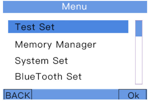 5.9.1 Test Condition Setting
5.9.1.1 Material Setting
Press the ![]() key, select Test Set and confirm, then Material Set. You can then select from the following options: steel and cast steel, alloy tool steel, cast aluminum alloy, gray cast iron, nodular cast iron, stainless steel, copper zinc alloy, copper tin alloy and pure copper. In the strength mode, the options of carbon steel, chromium steel, chromium vanadium steel, chromium nickel steel, chromium molybdenum steel, chromium nickel molybdenum steel, chromium manganese silicon steel, ultra-high strength steel and stainless steel are available.
key, select Test Set and confirm, then Material Set. You can then select from the following options: steel and cast steel, alloy tool steel, cast aluminum alloy, gray cast iron, nodular cast iron, stainless steel, copper zinc alloy, copper tin alloy and pure copper. In the strength mode, the options of carbon steel, chromium steel, chromium vanadium steel, chromium nickel steel, chromium molybdenum steel, chromium nickel molybdenum steel, chromium manganese silicon steel, ultra-high strength steel and stainless steel are available.
5.9.1.2 Times Setting
Press the ![]() key and select Test Set. After pressing OK, select Times Set to set the number of measurements required to calculate an average. This can be set from 1-32 times, a greater number of points will reduce the amount of data groups that can be saved.
key and select Test Set. After pressing OK, select Times Set to set the number of measurements required to calculate an average. This can be set from 1-32 times, a greater number of points will reduce the amount of data groups that can be saved.
5.9.1.3 Setting Limits
Press the ![]() key, select Test Set then press OK to select Limit Set. Enter the set limit then set the upper and lower limits of the measured values. (refer to 5.9.2.3 if an alarm is required when exceeding the limit).
key, select Test Set then press OK to select Limit Set. Enter the set limit then set the upper and lower limits of the measured values. (refer to 5.9.2.3 if an alarm is required when exceeding the limit). 5.9.1.4 Hardness / Strength Setting
Press the ![]() key, select Test Set. Press confirm, then select the Hardness / Strength, to select
key, select Test Set. Press confirm, then select the Hardness / Strength, to select
whether to measure hardness or strength.
5.9.2 Storage Management
The instrument can store up to 100 groups of hardness or strength measurement data depending on the number of points taken for each group.
Each group of data includes single measurement values, average value, impact direction, times, material, hardness system and impact device model.
Press the ![]() key, select Memory Manager. Press the OK key to enter, select the measurement data, then press the OK key to view the relevant measurement data.
key, select Memory Manager. Press the OK key to enter, select the measurement data, then press the OK key to view the relevant measurement data.
Once the instrument has stored 100 groups of data, new data can no longer be saved, and the storage flag icon on the screen will turn red and flash three times to notify the user that the data has not been saved. Stored data must be deleted to save any new data. To delete stored data press the ![]() key in the storage management to delete all data.
key in the storage management to delete all data.
5.9.3 System Setting
The device can be configured with preferred user settings, such as Automatic Storage, Key Sound, Warning Switch, LCD Brightness, Automatic Shutdown, Time Setting, Language and Additional Options.
5.9.3.1 Automatic Storage
Press the ![]() key, select System Setting, press confirm. Select Automatic Storage and press confirm. A tick mark will indicate if auto save is enabled. To cancel, press the OK key again.
key, select System Setting, press confirm. Select Automatic Storage and press confirm. A tick mark will indicate if auto save is enabled. To cancel, press the OK key again.
5.9.3.2 Key Sound
Press the ![]() key, select System Setting, press confirm. Select Key Sound and press the OK key. There will be check mark next to it, indicating that the key sound function is on. To cancel, press the OK key again, and the check box will disappear.
key, select System Setting, press confirm. Select Key Sound and press the OK key. There will be check mark next to it, indicating that the key sound function is on. To cancel, press the OK key again, and the check box will disappear.
5.9.3.3 Warning Switch
Press the ![]() key, select System Setting, press confirm. Select the Warning Switch and press the OK key, a check mark, indicates that the warning alarm is on. To cancel, press the OK key again, and the check box will disappear. If the warning switch is on, when the measured value exceeds the upper and lower limits the colour of the test value turns pink.
key, select System Setting, press confirm. Select the Warning Switch and press the OK key, a check mark, indicates that the warning alarm is on. To cancel, press the OK key again, and the check box will disappear. If the warning switch is on, when the measured value exceeds the upper and lower limits the colour of the test value turns pink.
5.9.3.4 LCD Brightness
Press the ![]() key, select System Setting, press OK. Select LCD Brightness and press the OK key.
key, select System Setting, press OK. Select LCD Brightness and press the OK key.
Then press ![]() and
and ![]() to set the brightness, 1- 5 where 5 is the brightest.
to set the brightness, 1- 5 where 5 is the brightest.
5.9.3.5 Automatic Shutdown
Press the ![]() key, select System Setting, press OK. Select Automatic Shutdown and press the OK key to select the time of automatic shutdown. When the device is not used it will shut down after the selected time of 2 minutes, 5 minutes, 10 minutes.
key, select System Setting, press OK. Select Automatic Shutdown and press the OK key to select the time of automatic shutdown. When the device is not used it will shut down after the selected time of 2 minutes, 5 minutes, 10 minutes.
5.9.3.6 Time Setting
Press the ![]() key, select System Setting. Press the confirm key. Select Time Setting and press
key, select System Setting. Press the confirm key. Select Time Setting and press ![]() then OK. Select the position to be set, press the
then OK. Select the position to be set, press the![]() keys, and then press the OK key to exit.
keys, and then press the OK key to exit.
5.9.3.7 Language
Press the ![]() key, select System Setting. Press the OK key. Select Language and press the OK key. Press
key, select System Setting. Press the OK key. Select Language and press the OK key. Press ![]() and
and ![]() to select English or Chinese,, and press the OK key to exit.
to select English or Chinese,, and press the OK key to exit.
5.9.4 Product Information
Press the ![]() key, select Product Information. Press the confirm key to view the relevant information of the instrument.
key, select Product Information. Press the confirm key to view the relevant information of the instrument.
Maintenance and Repair
6.1 Maintenance of Impact Device
- After 1000-2000 times of use, clean the conduit and impact body of the impact device with a nylon brush. When cleaning the conduit, first unscrew the support ring, then take out the impact body, twist the nylon brush counterclockwise into the tube, pull it out to the end, repeat this 5 times, and then re-install the impact body and support ring;
- Always release the impact device after loading.
- Cleaning fluids should not be used.
6.2 Precautions for Device Use
- Do not use the device in an environment with heavy dust or oily environments.
- When plugging in and removing the probe, hold the movable jacket still and apply force along the axis. Do not rotate the probe to avoid damaging the cable core of the probe.
- Any oil and dust may gradually damage the cable. After use, remove any contaminants from the cable.
6.3 Device Maintenance
- When a standard Rockwell hardness block is used for verification, if the error is greater than 2hrc, the ball joint may be worn, and the ball joint or impact probe should be replaced.
- Do not disassemble or adjust any fixed assembly parts.
Appendix
Table A-1
| No. | Material | HLD | σb(MPa) |
| 1 | C mild steel | 350 – 522 | 374 – 780 |
| 2 | C High carbon steel | 500 – 710 | 737 – 1670 |
| 3 | Cr | 500 – 730 | 707 – 1829 |
| 4 | CrV | 500 – 750 | 704 – 1980 |
| 5 | CrNi | 500 – 750 | 763 – 2007 |
| 6 | CrMo | 500 – 738 | 721 – 1875 |
| 7 | CrNiMo | 540 – 738 | 844 – 1933 |
| 8 | CrMnSi | 500 – 750 | 755 – 1993 |
| 9 | SSST | 630 – 800 | 1180 – 2652 |
| 10 | SST | 500 – 710 | 703 – 1676 |
Table A-2
| Impact Energy (mJ) | 11 |
| Impactor Mass (g) | 5.5g/7.2 |
| Ball Joint Hardness (HV) | 1600 |
| Ball Joint Diameter (mm) | 3 |
| Ball Joint Material | Tungsten Carbide |
| Impact Device Diameter (mm) | 20 |
| Length of Impact Device (mm) | 86(147)/ 75 |
| Weight of Impact Device (g) | 50 |
| Maximum Hardness of Test Piece (HV) | 940 |
| Average Surface Roughness of Test Piece Ra (μm) | 1.6 |
Table A-3
Minimum Test Piece Requirement
| Minimum Weight | >5 |
| Direct Measurement (kg) | 2 – 5 |
| Stable Support Required (kg) | 0.05 – 2 |
| Dense Coupling Required (kg) | |
| Minimum Thickness Dense Coupling (mm) | 5 |
| Minimum Depth of Hardened Layer (mm) | ≥0.8 |
Table A-4
Ball Joint Indentation Size
| Hardness 300HV | Diameter (mm) | 0.54 |
| Depth (μm) | 24 | |
| Hardness 600HV | Diameter (mm) | 0.54 |
| Depth (μm) | 17 | |
| Hardness 800HV | Diameter (mm) | 0.35 |
| Depth (μm) | 10 |
![]() MWT-3100 Leeb Hardness Tester
MWT-3100 Leeb Hardness Tester
INST-MWT-3100 – Iss 1
Documents / Resources
 |
MOORE AND WRIGHT MWT-3100 Leeb Hardness Tester [pdf] Instruction Manual MWT-3100, MWT-3100 Leeb Hardness Tester, Leeb Hardness Tester, Hardness Tester, Tester |