DICKSON TM320 Temperature and Humidity Data Logger With Display
Getting Started
Default Logger Settings
- 1 minute sample rate
- Wrap when full
- Degree F
Quick Start
Setup the logger by installing batteries.
Install DicksonWare™ software version 9.0 or higher. If already using DicksonWare, check the version by choosing “Help/About” from the menu bar. Contact Customer Service if an upgrade is required.
- Open DicksonWare using the icon on your desktop.
- Connect cable (supplied with DicksonWare software) to the logger and to a working Serial COM or USB port on your PC.
- Click Setup button in DicksonWare. At the prompt select USB or Serial COM port and click Continue. The Identification tab will open, and all fields should be automatically filled in. This confirms that DicksonWare™ has recognized the logger. Press the Clear button to delete all data currently stored on the logger. A Delta symbol I\. on the top left of the display indicates the unit is now logging.
NOTE: Should all fields remain blank, refer to “Logger will not communicate” in the Troubleshooting section of the manual.
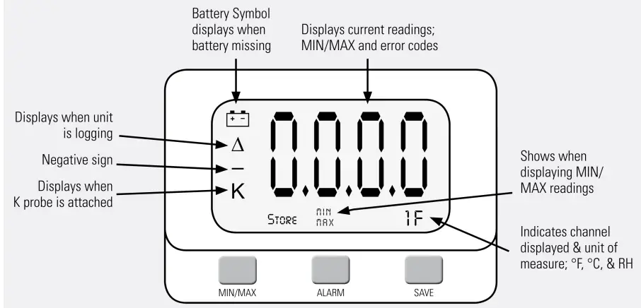
Display Functions
Save
Note: This feature is only for use with the Dickson provided memory cards or unlocked SD (secure digital) cards. Unauthorized cards may damage the unit.
Pressing this button will download any data stored in the logger to the removable memory card. “Store” will appear on the display momentarily and the counter will start counting down from 100. Do Not remove the memory card until “Store” is no longer displayed and the unit is displaying current readings.
Note: Leaving the memory card installed in the logger will reduce battery life by 50%. If you notice “Err” on the display, please refer to the Troubleshooting section of this manual.
Alarm
Pressing this button will silence the alarm. Holding this button down for about 5 seconds will toggle between “Fahrenheit” and “Celsius”. (Alarm parameters can only be set in DicksonWare™. Refer to the DicksonWare software manual.)
MINIMAX
When pressed, the display will scroll through MIN/MAX readings for each channel.
Clearing MINIMAX values
Holding the MIN/MAX and Alarm buttons down simultaneously until “cir” appears on display, will clear the stored minimum and maximum values. The MIN and MAX displayed by the logger will be the minimum and maximum values recorded since it was last cleared.
DicksonWare will show the MIN and MAX values for the entire downloaded data set. These could be different than those displayed on the unit itself if the MIN/MAX values were cleared at any time during logging.
Installing a Flash Memory Card Reader
Follow the instructions included with the flash card reader.
Power
These loggers operate on (4) AA batteries. An optional AC adapter ( Dickson part number R157) can be used for continuous power with battery backup.
Battery Replacement
- DicksonWare “setup” displays the battery voltage and a low battery warning when replacement is needed.
- When changing batteries, the logger will not collect data. However, memory will not be lost. To start sampling again, download data and then clear the memory using Dicksonware™.
Battery Life
The average battery life is 6 months. To achieve longer battery life during operation, use a less frequent sample rate and disconnect the unit from the USB or serial port when not downloading data.
Software
(All of these features can be modified by clicking on the main Setup button.)
Setup (button)
Click this button first to establish communication between your logger and DicksonWare™ software. You may be prompted to select the communication method between USB or Serial COM port. You may save this setting so you will not be prompted again. This setting is also changeable in File/Preferences/ Communications. A setup window will appear with “All fields” populated. This confirms that the software has recognized the logger. Should “All fields” remain blank and communication is not established, refer to the Troubleshooting section of this manual.
Identification (tab)
This tab provides you with the model and serial number of the logger, as well as the option to set a custom “User Id” by clicking the active “Setup” to the right of the “User Id” field. This tab also includes the date the unit was calibrated, calibration interval, and factory calibration date.
Samples (tab)
- The majority of the setup process takes place in this section. Each field with an active “Setup” button to the right, is a parameter that you can customize.
- Sample Interval Tells your logger how frequently you want it to take and store readings. This can be done in 10 or 1 second intervals. The dialog box that allows you to change the sample interval will also inform you how much time your chosen sample rate will cover. “Sub ten second interval” should be enabled for desired sample intervals with less than a 10 second interval.
- Stop or Wrap when Full Determines what the logger should do when it has collected all possible samples. The logger will either stop and discontinue logging, or continue logging by wrapping the newest data over the oldest.
Note: When changing logger settings (sample interval, stop/wrap, and start date and time) the logger will automatically clear all stored data.
Channels (tab)
By clicking the Adjust button to the right of the temperature or humidity value for each channel, you will be allowed to “Disable” a channel that is not necessary, change the name of a channel, set and activate “Alarm” parameters.
- TM320/325-Dnly the RH channel can be disabled
- SM320/325-0nly channel 2 can be disabled
Alarms (tab)
The alarms can only be set in DicksonWare™ in this section. You may enable or disable the alarms and their audio component and set the MIN and MAX values.
Download (button)
From the main menu, click on the Download button to automatically extract all logged data into a graph and table format. You may also choose to retrieve data via the optional Flash Memory card. After saving data to the card, simply insert the card into your reader, open the “LOD” folder, then double click on the appropriate “LOD” file which will automatically open DicksonWare™. If not, manually open DicksonWare™. From the top “Menu” bar, click on “File/Open” and browse to the appropriate drive for your reader. Select the “LOD” file. Double clicking on the graph after it has been opened gives you access to all the graph customization features.
Callbratlon
A “Zero Adjust” calibration can be performed on this logger. SW400 calibration software is required. Note: It is strongly recommended that a higher accuracy NIST’d instrument be used as the standard.
For more accurate calibration, return the instrument to Dickson for calibration in our A2LA Certified lab. Contact Customer Service for a Return Authorization Number before returning for calibration.
Need to know
Logger Settings
When changing logger settings (sample interval, sub 10 second interval and stop/wrap) the logger will automatically clear all stored data.
Fahrenheit/Celsius
- The data logger is defaulted to log data in “fahrenheit”. To change graph view in DicksonWare from “fahrenheit” to “celsius”, go to “File/ Preferences” to change temperature selection.
- To change display setting, hold down the Alarm button for about 5 seconds. The display will toggle between “F” and “C”.
Troubleshooting
Display Reads PROB
Models SM320/325 will display “Prob” if the thermocouple is not connected.
Logger will not communicate via Serial COM port connection
- Make sure you are using version 11 or higher of DicksonWare
- Verify that the correct COM port is selected. From the main Dicksonware screen, click on Logger, then Communication. A black dot will appear next to the selected COM port. You may need to select a different COM port. Should you get an error message stating that “Device Is Already Open”, this could mean that you do not have the proper COM port selected, but another device, or it’s software, has it allocated. Palm pilots, for example, will cause this problem, which in this case, the port is not actually “available” and you may have to disable that device.
- You may need to relocate the download cable to another serial port on the back of the PC and possibly try changing the COM port again in DicksonWare™.
- If communication has not been established with the previous steps, you may need to remove the batteries and then try all COM port and cable combinations again.
- If possible, try another PC
- Make sure that “USB” is not checked in File/Preferences/Communications.
Logger will not communicate via USB port connection
- Make sure that “USB” is selected under File/ Preferences/Communications.
- Unplug USB cable and plug back in.
- Remove all power to the logger. (This will not cause the unit to lose any data within the logger, but you will have to start the unit logging again using DicksonWare™.) Unplug the USB cable, power the logger back on, then reconnect the USB cable.
- If the logger was used in a moist or humid environment condensation may have formed on the unit. Place unit in a warm dry environment for 24 hours. Clear the memory and try again. These loggers are designed for use in a non-condensing environment. If the environment creates condensation, try placing the unit (temperature only models) in a small sealed plastic bag to protect it from condensation.
- If possible, try another PC, and/or another USB port and/or USB cable.
Err 14 Code Displayed-Will not save data to MMC card
This is a generic fault code. There is something wrong with the MMC card (full or not formated correctly) or there is a hardware issue (a bad connector or no card present – can”t see any card). Try another card (make sure is is an MMC card not an MMC Plus card). and that it has been supplied by Dickson. For additional information on formatting your own MMC card go to: http://www.DicksonData.com/misc/technical_support_model.php
Display reads 0
- Replace the batteries, they may be low.
- SM420-Unit is reading -400 when the probe is in an environment that is nowhere close to that temperature.
- The RTD probe on the SM420 is very delicate compared to a K-TC probe. Try removing any kinks and straightening the probe out. If the unit does not begin to display the correct temperature, the probe may have been permenantly damaged. Contact Customer Service to return for repair.
Logger is not Logging
- The logger will stop logging if power is removed. Change batteries or connect to AC power then via DicksonWare. Clear the logger to reset and start logging.
- The logger will stop logging if it is full of data and logger has been set to “Stop When Full” in DicksonWare™.
Additional technical support can be found at our website: http://www.DicksonData.com/info/support.php
Error Codes
- Err 1 …………………………….. No Memory Card
- Err 2 …………….. Memory card locked or protected
- Err 23 …………. Memory card required reformatting
- Err 66 …………………………… Memory card full
Warranty
- Dickson warrants that this line of instruments will be free from defects in material and workmanship under normal use and service for a period of twelve months after delivery.
- This warranty does not cover routine calibration and battery replacement.
- For Specifications and Technical Support go to www.DicksonData.com
Factory Service & Returns
Contact Customer Service 630.543.3747 for a Return Authorization Number (RA) before returning any instrument. Please have the model number, serial number and a PO ready before calling.
www.DlcksonData.com
930 South Westwood Avenue
- Addison, IL 60101-4917
- Telephone: 630.543.3747
- Fax: 630.543.0498
- E-mail: DicksonCSR@DicksonData.com
- www.DicksonData.com
- 1-800-323-2448
- Fax 1-800-676-0498
Documents / Resources
 |
DICKSON TM320 Temperature and Humidity Data Logger With Display [pdf] User Guide TM320, TM325, TM320 Temperature and Humidity Data Logger With Display, TM320, Temperature and Humidity Data Logger With Display, Humidity Data Logger With Display, Logger With Display, With Display, Display |