![]() DS3 Soldering Controller
DS3 Soldering Controller
Instruction Manual
DS3 Soldering Controller

Thank you for purchasing the OMEGA.
Read these instructions thoroughly for proper use of this machine. Make sure to read “Safety Notes” before you use machine. This information protects you from possible dangers during use.
Safety Notes
- This manual includes the important information to use this machine safely. This also includes useful information to prevent injury or damage to property. Please read this manual carefully prior to connecting or operating the OMEGA.
- Keep this manual near the machine at all times.
Supply only specified voltage - Do not connect to a power supply greater than the specified voltage. If voltage is exceeded, electrical shock and /or damage to the unit may occur.
- Make sure that the electrical outlet is properly grounded. If the outlet is not properly grounded, electrical shock and/or damage to the unit may occur.
Working ambient temperature and relative humidity - This machine has been designed for use between 10~40 degrees C,10%~85%.
- Do not use this machine exceeding these conditions.
Setting temperature of the heater controller - Do not set the temperature of the heater controller over 500 degrees C. It may cause a malfunction.
Handle with care - This machine is designed to use a solder feeder and hot iron for soldering. Touching a heated soldering iron will cause severe burns. Make sure the iron hascooled down before you are touching it for replacing the iron cartridge.
- Please handle this machine with care. If the machine is dropped or sustains great impact / vibration, it may cause malfunction. If you do not use the machine for a long time
- Please turn off the power, remove the power cable and keep it in a dry and cool place.
If you note malfunction on machine - If the machine malfunctions, turn off the power immediately and contact the dealer you purchased the machine from.
The warranty period - The warranty period is one year after the product is delivered.
If an unexpected malfunction which our company bears responsibility occurs within the warranty period, we repair it in free of charge.
Immunity from responsibility
- We do not take any responsibility for damage caused by misuse, mistakes, accidents, use in abnormal conditions or natural disasters, such as in an earthquake, a fire etc.
- We do not take any responsibility on contingency loss, (Business loss, Business stop, Overtime, Scrap or Reduced Output) caused by a machine stoppage or any issues with Apollo Seiko spare & consumable parts.
- We do not take any responsibility for losses or damages caused by operating with other means not mentioned in this manual.
- We do not take any responsibility for losses or damages caused by a wrong connection with other equipment.
- If for any reason the internal circuitry is tampered with altered or repaired without written consent of Apollo Seiko, the warranty is null and void. The customer is allowed to make necessary tooling adjustments, replace solder iron tips and make any necessary adjustments to the temperature controller.
11. External Controller Communication Specifications
11.1 Serial Communication Specifications
Communication standard:RS-232C
Communication protocol Non-procedure
Connecting number:1 on 1
Synchronization system: Start – Stop Synchronization system
Transmission code ASCII
Interface Triple wire system (TxD / RxD / GND)
Communication speed:9600bps
Start bit length:1 bit (Fixed)
Stop bit length:8 bit
Parity None
Response delay time:0~250ms’
11.2 Communication Format All communication is STX + Main unit text + ETX + SUM format.
| STX | Main text | ETX | SUM (Higher) | SUM (Lower) |
The SUM is the value that results from adding the decimal values of the characters in the main text, converting them to hexadecimal and then adding the resulting 2 bytes after ETX.
When the SUM exceeds the 8 bits data length, only the two least significant values must be kept.
For instance, if SUM is 1526 equaling to 5F6h in hexadecimal which exceeds the 8-bit limit, for this case, only the two less significant digits will be taken into account(“F6”), which are the two bytes that will be added (using English capital characters) after ETX.
If the added SUM value to the command and the calculated SUM value do not match, the command is treated as unauthorized data, is ignored and deleted. When this happens, the command is discarded and re-transmission request is not performed.
SUM value calculation example In case of STX + [K12C] + ETX + SUM 75(4Bh) + 49(31h) + 50(32h) + 67(43h) = 241(F1h)
| STX | ‘K’ | ‘1’ | ‘2’ | ‘C’ | ETX | ‘F’ | ‘1’ |
| 02h | 4Bh | 31h | 32h | 43h | 03h | 46h | 31h |
11.3 Various Commands
11.3.1 A : Soldering Controller Information Request
| 【Code】 | 41H(‘A’) |
| 【Function】 | Soldering controller information request |
| 【Direction】 | External controller → Soldering controller |
| 【Data】 | None |
| 【Explanation】 | It checks the state of the soldering controller (solder shortage / solder clogged). When the soldering controller receive this command, it returns “a” command. |
| 1 | 2 | 3 | 4 | 5 |
| STX | ‘A’ | ETX | SUM | |
11.3.2 a : Soldering Controller Information Request Reply
| 【Code】 | 61H(‘a’) |
| 【Function】 | Soldering controller information request return |
| 【Direction】 | Soldering controller → External controller |
| 【Data】 | State (0:Normal, 1:Solder shortage, 2:Solder clogged, 3:Solder shortage & Solder clogged) |
| 【Explanation】 | It is a reply to A command from the external controller. |
| 1 | 2 | 3 | 4 | 5 | 6 |
| STX | ‘a’ | state | ETX | SUM | |
11.3.3 B : Temperature Control State Request
| 【Code】 | 42H(‘B’) |
| 【Function】 | Temperature control state request |
| 【Direction】 | External controller → Soldering controller |
| 【Data】 | None |
| 【Explanation】 | It checks the operation state of the temperature controller of the soldering controller. When the soldering controller receive this command, it returns “b”. |
| 1 | 2 | 3 | 4 | 5 |
| STX | ‘B’ | ETX | SUM | |
11.3.4 b : Temperature Control State Request Reply
| 【Code】 | 62H(‘b’) |
| 【Function】 | Temperature control state request return |
| 【Direction】 | Soldering controller → External controller |
| 【Data】 | 0:Ready or Normal, 1: in Preparation / Error (*Ready or Normal: Condition of READY Signal High) |
| 【Explanation】 | It is a reply to B command from the external controller. |
| 1 | 2 | 3 | 4 | 5 | 6 |
| STX | ‘b’ | State | ETX | SUM | |
11.3.5 C : Solder Condition Transfer Request
| 【Code】 | 43H(‘C’) |
| 【Function】 | Solder condition transfer request |
| 【Direction】 | External controller → Soldering controller |
| 【Data】 | Solder condition number |
| 【Explanation】 | It requests the solder condition saved in the soldering controller. The solder condition number is specified by hexadecimal / 4 digits (2 Byte). e.g.: When the solder condition is 124, it specifies 007CH. |
| 1 | 2 | 3 | 4 | 5 | 6 | 7 | 8 | 9 |
| STX | ‘C’ | Solder condition number | ETX | SUM | ||||
11.3.6 c : Solder Condition Data Transfer Request
| 【Code】 【Function】 【Direction】 |
63H(‘c’) Solder condition data transfer request Soldering controller → External controller |
|
| 【Data】 | Solder condition number 000, 101~199, 201~299, 301~399
Solder mode 0, 1, 2, 3, 4, 5 |
4 Byte
1 Byte |
| SV2 setting temperature rising time | 3 Byte | |
| 1st solder wire feeding amount | 3 Byte | |
| 1st solder wire feeding speed | 3 Byte | |
| 1st solder wire reversing amount | 3 Byte | |
| 1st solder wire reversing speed | 3 Byte | |
| Pre-heating time | 3 Byte | |
| 2nd solder wire feeding amount | 3 Byte | |
| 2nd solder wire feeding speed | 3 Byte | |
| 2nd solder wire reversing amount | 3 Byte | |
| 2nd solder wire reversing speed | 3 Byte | |
| Heating time | 3 Byte | |
| 3rd solder wire feeding amount | 3 Byte | |
| 3rd solder wire feeding speed | 3 Byte | |
| 3rd solder wire reversing amount | 3 Byte | |
| 3rd solder wire reversing speed | 3 Byte | |
| Solder pool time | 3 Byte |
【Explanation】
It is a return to C command from the external controller.
It is hexadecimal / 3 digits notation except for Solder condition number and Solder mode.
It is hexadecimal / 4 digits notation in Solder condition number.
It is hexadecimal / 1 digit notation in Solder mode.
The value divided by 10 after converted it to decimal numbers becomes the actual setting value.
If it specifies a solder condition number that does not exist in C command, it ignores the command.
The number of Solder mode is as following;
0: Special point soldering
1: Special slide soldering
2: Special soldering point soldering (without iron up motion)
3: Special easy slide soldering
4: Pre-solder
5: Set Temp
When solder mode is “5: Set Temp”, it returns the set temperature and the process of set temperature.
| Set temperature | 3 Byte |
| Process of set temperature | 3 Byte |
When solder condition number is 0, it returns the air blow time of cleaning.
| Solder condition number | 0 | 4 Byte |
| Air blow time | 3 Byte |
Except for Set Temp / Cleaning Operation
| 1 | 2 | 3 | 4 | 5 | 6 | … | 54 | 55 | 56 |
| STX | ‘c’ | Solder condition number | … | ETX | SUM | ||||
Set Temp Operation
| 1 | 2 | 3 | 4 | 5 | 6 | … | 12 | 13 | 14 |
| STX | ‘c’ | Solder condition number | … | ETX | SUM | ||||
Cleaning Operation
| 1 | 2 | 3 | 4 | 5 | 6 | 7 | 8 | 9 | 10 | 11 | 12 |
| STX | ‘c’ | ‘0’ | ‘0’ | ‘0’ | ‘0’ | Air blow time | ETX | SUM | |||
11.3.7 D : Solder Condition Data Transfer Request
| 【Code】 【Function】【Direction】 |
44H(‘D’) Solder Condition Data Transfer Request External controller → Soldering controller |
|
| 【Data】 | Solder condition number 000, 101~199, 201~299, 301~399 Solder mode 0, 1, 2, 3, 4, 5 |
4 Byte 1 Byte |
| SV2 setting temperature rising time | 3 Byte | |
| 1st solder wire feeding amount | 3 Byte | |
| 1st solder wire feeding speed | 3 Byte | |
| 1st solder wire reversing amount | 3 Byte | |
| 1st solder wire reversing speed | 3 Byte | |
| Pre-heating time | 3 Byte | |
| 2nd solder wire feeding amount | 3 Byte | |
| 2nd solder wire feeding speed | 3 Byte | |
| 2nd solder wire reversing amount | 3 Byte | |
| 2nd solder wire reversing speed | 3 Byte | |
| Heating time | 3 Byte | |
| 3rd solder wire feeding amount | 3 Byte | |
| 3rd solder wire feeding speed | 3 Byte | |
| 3rd solder wire reversing amount | 3 Byte | |
| 3rd solder wire reversing speed | 3 Byte | |
| Solder pool time | 3 Byte |
【Explanation】
It sets a solder condition from external controller to soldering controller.
It is hexadecimal / 3 digits notation except for Solder condition number and Solder mode.
If the data has a decimal point, the value that omitted decimal point is expressed in hexadecimal.
Example 1: 3.5s⇒35(23H), Example 2: 10.0s⇒100(64H) It is hexadecimal / 4 digits notation in Solder condition number.
It is hexadecimal / 1 digit notation in Solder mode.
The value divided by 10 after converted it to decimal numbers becomes the actual setting value.
If it specifies a solder condition number that does not exist, it ignores the command.
If it specifies a solder mode that does not exist, it ignores the command.
If a data is outside the range, it ignores the command.
The number of Solder mode is as following;
0: Special point soldering
1: Special slide soldering
2: Special soldering point soldering (without iron up motion)
3: Special easy slide soldering
4: Pre-solder
5: Set Temp
* The value in case of Point soldering and Slide soldering is not fixed.
When solder mode is “5. Set Temp”, it sets the set temperature and the process of set temperature.
| Set temperature | 3 Byte |
| Process of set temperature | 3 Byte |
When solder condition number is 0, it sets the air blow time of cleaning
| Solder condition number | 4 Byte |
| Air blow time | 3 Byte |
Except for Set Temp / Cleaning Operation
| 1 | 2 | 3 | 4 | 5 | 6 | … | 54 | 55 | 56 |
| STX | ‘D’ | Solder condition number | … | ETX | SUM | ||||
Set Temp Operation
| 1 | 2 | 3 | 4 | 5 | 6 | … | 12 | 13 | 14 |
| STX | ‘D’ | Solder condition number | … | ETX | SUM | ||||
Cleaning Operation
| 1 | 2 | 3 | 4 | 5 | 6 | 7 | 8 | 9 | 10 | 11 | 12 |
| STX | ‘D’ | ‘0’ | ‘0’ | ‘0’ | ‘0’ | Air blow time | ETX | SUM | |||
11.3.8 d : Soldering Condition Data Request Reply
| 【Code】 | 64H(‘d’) |
| 【Function】 | Soldering condition data request return |
| 【Direction】 | Soldering controller → External controller |
| 【Data】 | None |
| 【Explanation】 | It is a reply from an external controller to D command. It responds when D command is received normally. |
| 1 | 2 | 3 | 4 | 5 |
| STX | ‘d’ | ETX | SUM | |
11.3.9 F : Special Soldering Set Temp State Request
| 【Code】 | 46H(‘F’) |
| 【Function】 | Set Temp state request |
| 【Direction】 | External controller → Soldering controller |
| 【Data】 | None |
| 【Explanation】 | The external controller requests Set Temp state to the soldering controller. |
| 1 | 2 | 3 | 4 | 5 |
| STX | ‘F’ | ETX | SUM | |
11.3.10 f : Special Soldering Set Temp State Report
| 【Code】 | 66H(‘f’) |
| 【Function】 | Set Temp state report |
| 【Direction】 | Soldering controller → External controller |
| 【Data】 | State In case of Range, No Check When “Alarm Temperature Range Low < PV < Alarm Temperature Range High”, it returns 0. Except for it, it returns 1. In case of Setting Value When PV judges as optimal temperature, it returns 0. Except for it, it returns 1. |
| 【Explanation】 | It replies Set Temp state to F command that is from the upper controller. |
| 1 | 2 | 3 | 4 | 5 | 6 |
| STX | ‘f’ | State | ETX | SUM | |
11.3.11 G : Solder Mode Only Transfer Request
| 【Code】 | 47H(‘G’) |
| 【Function】 | Solder mode only transfer request |
| 【Direction】 | External controller → Soldering controller |
| 【Data】 | None |
| 【Explanation】 |
| 1 | 2 | 3 | 4 | 5 |
| STX | ‘G’ | ETX | SUM | |
11.3.12 g : Solder Mode Only Transfer Request Return
| 【Code】 | 67H(‘g’) |
| 【Function】 | Solder mode only transfer request return |
| 【Direction】 | Soldering controller → External controller |
| 【Data】 | Solder mode only |
| 【Explanation】 | It returns solder mode number of Solder condition number 301~399 as continuous data |
| 1 | 2 | 3 | … | … | 102 | 103 | 104 | 105 |
| STX | ‘g’ | Solder mode number | ETX | SUM | ||||
11.3.13 H : Soldering Execution
| 【Code】 | 48H(‘H’) |
| 【Function】 | Soldering execution |
| 【Direction】 | External controller → Soldering controller |
| 【Data】 | Solder condition number |
| 【Explanation】 | The external controller requests to the soldering controller to execute soldering. When specifying a solder condition number that does not exist, it ignores the command. In case of Point soldering, it returns h command after a series of soldering operation is completed. In case of Slide soldering, it returns i command when 1st soldering is completed. |
| 1 | 2 | 3 | 4 | 5 | 6 | 7 | 8 | 9 |
| STX | ‘H’ | Solder condition number | ETX | SUM | ||||
11.3.14 h : Soldering Completion Report
| 【Code】 | 68H(‘h’) |
| 【Function】 | Soldering completion report |
| 【Direction】 | Soldering controller → External controller |
| 【Data】 | None |
| 【Explanation】 | It returns completion of soldering operation to H command that is from the upper controller. In case of Slide soldering, This command is not returned. |
| 1 | 2 | 3 | 4 | 5 |
| STX | ‘h’ | ETX | SUM | |
11.3.15 I : Slide Soldering Start Request
| 【Code】 | 49H(‘I’)、4AH(‘J’) |
| 【Function】 | I: Slide soldering start request |
| 【Direction】 | External controller → Soldering controller |
| 【Data】 | None |
| 【Explanation】 | Refer to “13.2 Slide Soldering Operation” about operation. |
| 1 | 2 | 3 | 4 | 5 |
| STX | ‘I’ | ETX | SUM | |
| 1 | 2 | 3 | 4 | 5 |
| STX | ‘J’ | ETX | SUM | |
11.3.16 i: Slide Soldering 1st Feeding Completion Report, j: Slide Soldering Pre-heat Completion Report, k: Slide Soldering Completion Report
| 【Code】 | 69H(‘i’)、6AH(‘j’)、6BH(‘k’) |
| 【Function】 | i: Slide soldering 1st feeding completion report j: Slide soldering pre-heat completion report k: Slide soldering completion report |
| 【Direction】 | Soldering controller → External controller |
| 【Data】 | None |
| 【Explanation】 | Refer to “13.2 Slide Soldering Operation” about operation. |
| 1 | 2 | 3 | 4 | 5 |
| STX | ‘i’ | ETX | SUM | |
| 1 | 2 | 3 | 4 | 5 |
| STX | ‘j’ | ETX | SUM | |
| 1 | 2 | 3 | 4 | 5 |
| STX | ‘k’ | ETX | SUM | |
11.3.17 N : Easy Slide Soldering Completion Report
| 【Code】 | 4EH(‘N’) |
| 【Function】 | Easy slide soldering completion report |
| 【Direction】 | External controller → Soldering controller |
| 【Data】 | None |
| 【Explanation】 | Refer to “13.6 Special Soldering Easy Slide Soldering Operation” about operation. |
| 1 | 2 | 3 | 4 | 5 | 6 | 7 | 8 |
| STX | ‘K’ | Set temperature | ETX | SUM | |||
11.3.18 K : Temperature Controller SV Change
| 【Code】 | 4BH(‘K’) |
| 【Function】 | Temperature controller SV change |
| 【Direction】 | External controller → Soldering controller |
| 【Data】 | Temperature 3 digits (hexadecimal notation) |
| 【Explanation】 | A specified temperature is set to “Setting temperature” of system parameter. When it is a value above the maximum temperature setting, it will not set. |
| 1 | 2 | 3 | 4 | 5 |
| STX | ‘P’ | ETX | SUM | |
11.3.19 P : Manual Solder Feeding Start
| 【Code】 | 50H(‘P’) |
| 【Function】 | Manual solder feeding start |
| 【Direction】 | External controller → Soldering controller |
| 【Data】 | None |
| 【Explanation】 | When it receives this command while automatic operation is stopping, it starts to feed the solder wire. It continues to feed the solder until it receives Manual solder feeding end command. |
| 1 | 2 | 3 | 4 | 5 |
| STX | ‘Q’ | ETX | SUM | |
11.3.21 R : Manual Solder Reversing Start
| 【Code】 | 52H(‘R’) |
| 【Function】 | Manual solder reversing start |
| 【Direction】 | External controller → Soldering controller |
| 【Data】 | None |
| 【Explanation】 | If it receives this command while automatic operation is stopping, it starts solder reversing. If it receives this command while manual solder feeding is stopped, it ignores the command. |
| 1 | 2 | 3 | 4 | 5 |
| STX | ‘R’ | ETX | SUM | |
11.3.22 S : Manual Solder Reversing End
| 【Code】 | 53H(‘S’) |
| 【Function】 | Manual solder reversing end |
| 【Direction】 | External controller → Soldering controller |
| 【Data】 | None |
| 【Explanation】 | If it receives this command while manual solder reversing, it stops manual solder reversing. If it receives this command during automatic solder feeding, it ignores the command. |
| 1 | 2 | 3 | 4 | 5 |
| STX | ‘R’ | ETX | SUM | |
11.3.23 T : Manual Air Blow Start
| 【Code】 | 54H(‘T’) |
| 【Function】 | Manual air blow start |
| 【Direction】 | External controller → Soldering controller |
| 【Data】 | None |
| 【Explanation】 | It outputs air blow. |
| 1 | 2 | 3 | 4 | 5 |
| STX | ‘S’ | ETX | SUM | |
11.3.24 U : Manual Air Blow End
| 【Code】 | 55H(‘U’) |
| 【Function】 | Manual air blow end |
| 【Direction】 | External controller → Soldering controller |
| 【Data】 | None |
| 【Explanation】 | It stops air blow output. |
| 1 | 2 | 3 | 4 | 5 |
| STX | ‘U’ | ETX | SUM | |
11.3.25 V: Manual Iron Up
| 【Code】 | 56H(‘V’) |
| 【Function】 | Manual iron up |
| 【Direction】 | External controller → Soldering controller |
| 【Data】 | None |
| 【Explanation】 | If it receives this command while automatic operation is stopping, it rises the iron. It does not judge “Iron up/down sensor error limit” in this command. |
| 1 | 2 | 3 | 4 | 5 |
| STX | ‘V’ | ETX | SUM | |
11.3.26 W: Manual Iron Down
| 【Code】 | 57H(‘W’) |
| 【Function】 | Manual iron down |
| 【Direction】 | External controller → Soldering controller |
| 【Data】 | None |
| 【Explanation】 | If it receives this command while automatic operation is stopping, it lowers the iron. It does not judge “Iron up/down sensor error limit” in this command. |
| 1 | 2 | 3 | 4 | 5 |
| STX | ‘W’ | ETX | SUM | |
11.3.27 Y: Emergency Stop
| 【Code】 | 59H(‘Y’) |
| 【Function】 | Emergency stop |
| 【Direction】 | External controller → Soldering controller |
| 【Data】 | None |
| 【Explanation】 | It informs emergency stop to the soldering controller. |
| 1 | 2 | 3 | 4 | 5 |
| STX | ‘Y’ | ETX | SUM | |
11.3.28 Z: Reset
| 【Code】 | 5AH(‘Z’) |
| 【Function】 | Reset |
| 【Direction】 | External controller → Soldering controller |
| 【Data】 | None |
| 【Explanation】 | It informs reset to the soldering controller. |
| 1 | 2 | 3 | 4 | 5 |
| STX | ‘Z’ | ETX | SUM | |
I/O Assignment
12.1 Terminal Arrangement of the Connector
| Signal Name | |||
| 40 | 0V | 39 | |
| 38 | 0V | LINE MOVE END | 37 |
| 36 | SEL200 | 35 | |
| 34 | EXT24V | SEL100 | 33 |
| 32 | 24V | AIR BLOW | 31 |
| 30 | 24V | IRON U/D | 29 |
| 28 | S- | 27 | |
| 26 | S+ | 25 | |
| 24 | RESET | 23 | |
| 22 | AUX OUT | STOP | 21 |
| 20 | START | 19 | |
| 18 | 17 | ||
| 16 | SEL64 | 15 | |
| 14 | IRON UNIT ERROR | SEL32 | 13 |
| 12 | SOLDER ERROR | SEL16 | 11 |
| 10 | ACK | SEL8 | 9 |
| 8 | END | SEL4 | 7 |
| 6 | RUNNING | SEL2 | 5 |
| 4 | READY | SEL1 | 3 |
| 2 | EMR | EMR | 1 |
 Connector XG4A-4034(OMRON)
- The connection harness should be provided by end user.
The power source and polarity of I/O can be switched by the switch on the circuit board.
| Switch Number | Contents | When ON | When OFF |
| DS1 | Switching supply power source | External power supply | Internal power supply |
| DS2 | External device output unit specification (PLC etc.) | NPN | PNP |
| DS3 | External device input unit specification (PLC etc.) | PNP | NPN |
 These switches are on the circuit board in the left side cover of the controller.
12.2 Internal Circuit Diagram (Pattern Diagram) 
For both external power source and internal power source, please make sure that the current value of I/O pin should be used under the following condition;
Input side Under 5mA Output side Under 100mA
When the external power source is used, please use it at the voltage within the range of 24V±10%.
12.3 Digital Input Signal
| Pin No. | Terminal name | Signal name | Description |
| 1 | EMR | Emergency stop | The machine stops at emergency. It is usually used ON of no voltage. If this terminal is released, all of the soldering operation stop and the heater is turned OFF. After shortening (when STA setting), input the reset signal. |
| 2 | |||
| 3 | SEL1 | Prog. select 1 | Select soldering condition number. Set soldering condition number combining with SEL100 and SEL200 by binary number. It is set by ON. 000 Cleaning WK100 101~199 Point soldering WK101~199 201~299 Slide soldering WK201~299 301~399 Special soldering WK301~399 Setting example Cleaning WK100: All OFF\ Point soldering WK101: SEL100 and SEL1 are ON Slide soldering WK205: SEL200, SEL1, SEL4 are ON |
| 5 | SEL2 | Prog. select 2 | |
| 7 | SEL4 | Prog. select 4 | |
| 9 | SEL8 | Prog. select 8 | |
| 11 | SEL16 | Prog. select 16 | |
| 13 | SEL32 | Prog. select 32 | |
| 15 | SEL64 | Prog. select 64 | |
| 19 | START | Start signal | It starts automatic operation.\ Signal is input by the sensor, switch, etc. (Minimum pulse width is more than 100ms.) When READY output is ON, it accepts input. |
| 21 | STOP | Stop signal | Automatic operation stops.
(Minimum pulse width is more than 100ms.) |
| 23 | RESET | Reset signal | It returns from Emergency stop or Error condition except for Heater Error. Input the signal after releasing Emergency stop or Error condition. (Minimum pulse width is more than 100ms.) (To reset Heater Error except for Temperature Alarm, restart the device.) |
| 25 | S+ | Solder feeding forward | It feeds solder wire forward from the feeder. Feeding speed can be set by Ms-speed of the system parameter. (Do not input ON at the same time with S-.) |
| 27 | S- | Solder feeding reverse | It reverses solder wire to the feeder. Reverse speed can be set by Ms-speed of the system parameter. (Do not input ON at the same time with S+.) |
| 29 | IRON U/D | Iron unit up/ down | It operates the iron unit up and down. ON: Iron down OFF: Iron up |
| 31 | AIR BLOW | Air blow | It operates air blow for tip cleaning at ON. |
| 33 | SEL100 | Prog. select 100 | Select soldering condition number combining with SEL1 ~ 64. When SEL100 is ON with SEL1 ~ 64, 100 is added. When SEL200 is ON with SEL1 ~ 64, 200 is added. When both SEL100 and SEL200 are ON, 300 is added. |
| 35 | SEL200 | Prog. select 200 | |
| 37 | LINE MOVE END | End of slide soldering | It stops Easy Line soldering of Special soldering. |
| 30 | 24V | DC24V output | It is DC24V output by internal power supply of OMEGA. The max. power supply current is 500mA. |
| 32 | |||
| 34 | EXT 24V | External power supply input | 24V input for external power supply. When you use this input, open the side cover and slide DIP switch on the circuit board to the external input side. The DIP switch is set as internal power supply at factory setting. |
- When Type of system parameter is set to COM / LAN, the function corresponds to each item of Digital input signal does not operate. (Except for Emergency Stop)
- When Type of system parameter is set to I/O / LAN and if any of FEED+, FEED-, S+ and S- are input at the same time, it operates with following the input that has been received earlier. It ignores the signal that has been input later.
(When it is set to LAN, it judges by using data that S+ & S- received by Modbus TCP communication.) - ON Contact ON OFF Contact OFF
12.4 Digital Output Signal
| Pin No. | Terminal name | Signal name | Description |
| 4 | READY | Ready signal | It turns on, when automatic operation is ready. |
| 6 | RUNNING | Running signal | It turns on during automatic operation. |
| 8 | END | Operation end signal | It turns on when automatic operation ends. (ON time approx. 100ms) |
| 10 | ACK | ACK output | It outputs the timing of axis moving at slide soldering. It turns ON, after the time that is set on STEP 4 ACK of WK setting.. (ON time approx. 100ms) |
| 12 | SOLDER ERROR | Solder error signal | It outputs at solder shortage or solder clogged. It automatically returns, when new solder wire is replaced at solder shortage. Remove clogged solder and input RESET signal at solder shortage. |
| 14 | IRON UNIT ERROR | Iron unit error signal | It turns on at normal state. Temperature error: it turns off, when the temperature exceeds temperature alarm range set on the system parameter. The display turns in orange color. The error is automatically released after the temperature is recovered. Iron unit U/D: It turns off, when iron unit up/ down sensor does not work. Input RESET signal after error cause are solved. |
| 22 | COUNTER OUT | External output 1 | This output is for iron shot counter. It turns on at the end of the cycle excluding cleaning. (ON time approx. 100ms) |
| 38 | 0V | 0V COM | The 0V COM is common to both Internal and External power supply. |
| 40 |
- It also outputs when Type of system parameter is set to ROB.
- Refer to “13. Soldering Operation” about the timing and condition of output.
Soldering Operation
Soldering operation operates with following a command from I/O port, serial communication port or Ether communication port.
It cannot use I/O port and serial communication port at the same time.
It can select which port (I/O, COM or LAN) is to be used at “Type” of system parameter.
When it receives any information signal or command that is not selected, it is ignored.
It starts soldering operation after it detects HIGH of START signal. After it started, it waits until the temperature input value comes within the range of the optimal limit sensitivity setting value.
13.1 Point Soldering Operation
13.1.1 Soldering Operation by I/O port
- Specify a solder condition number by SEL1, SEL2, SEL4, SEL8, SEL16, SEL32, SEL64, SEL100 and SEL200.
- Start the soldering operation by START signal. (Delay of more than 100msec is necessary from solder condition number specification)
- When it receives START signal, READY signal becomes LOW.
- When it receives START signal, RUNNING signal becomes High.
- It starts to solder.
- When soldering is completed, COUNTER OUT is outputted as a pulse.
- After COUNTER OUT is outputted as a pulse, END is outputted as a pulse.
- After COUNTER OUT is outputted as a pulse, READY signal becomes High.
- After COUNTER OUT is outputted as a pulse, RUNNING signal becomes LOW.
* It is not necessary that START signal is outputted as a pulse. (Except for LAN operation)
Soldering operation is as following.
- It controls the temperature to 2nd temperature control setting temperature or setting temperature.
- It feeds solder wire in accordance with 1st solder amount / speed setting.
- It reverses solder wire in accordance with 1st solder amount / speed setting.
- It lowers the iron.
- It waits according to pre-heat time setting.
- It feeds solder wire in accordance with 2nd solder amount / speed setting.
- It reverses solder wire in accordance with 2nd solder amount / speed setting.
- It waits according to heat time setting.
- It rises the iron.
- It controls the temperature to the setting temperature or wait temperature setting. (When wait time is set, it controls the temperature after the wait time passed.)
13.1.2 Soldering Operation by Serial Communication Port
It needs to set a suitable WK No. in Solder condition setting in advance. 13.2 Slide Soldering Operation
13.2.1 Soldering Operation by I/O Port 
- Specify a solder condition number by SEL1, SEL2, SEL4, SEL8, SEL16, SEL32, SEL64, SEL100 and SEL200.
- Start the soldering operation by START signal. (Delay of more than 100msec is necessary from solder condition number specification)
- When it receives START signal, READY signal becomes LOW.
- When it receives START signal, RUNNING signal becomes High.
- It prepares to solder.
- When soldering preparation is completed, ACK is outputted as a pulse.
- It starts to solder.
- When soldering is completed, COUNTER OUT is outputted as a pulse.
- After COUNTER OUT is outputted as a pulse, END is outputted as a pulse.
- After COUNTER OUT is outputted as a pulse, READY signal becomes High.
- After COUNTER OUT is outputted as a pulse, RUNNING signal becomes LOW.
* It is not necessary that START signal is outputted as a pulse. (Except for LAN operation)
The soldering preparation is as following.
- It controls the temperature to 2nd temperature control setting temperature or setting temperature.
- It feeds solder wire in accordance with 1st solder amount / speed setting.
- It reverses solder wire in accordance with 1st solder amount / speed setting.
- It lowers the iron.
- It waits according to pre-heat time.
Soldering operation is as following.
- It feeds solder wire in accordance with 2nd solder amount / speed setting.
- It reverses solder wire in accordance with 2nd solder amount / speed setting.
- It waits according to heat time setting.
- It feeds solder wire in accordance with 3rd solder amount / speed setting.
- It reverses solder wire in accordance with 3rd solder amount / speed setting.
- It rises the iron.
- It controls the temperature to the setting temperature or wait temperature setting. (When wait time is set, it controls the temperature after the wait time passed.)
13.2.2 Soldering Operation by Serial Communication Port
It needs to set a suitable WK No. in Solder condition setting in advance. Continue from the previous page
 13.3 Special Soldering Point Soldering Operation
13.3.1 Soldering Operation by I/O Port
Refer to “13.1.1 Soldering Operation by I/O Port” about timing chart and timing.
Soldering operation is as following.
- It controls the temperature to 2nd temperature control setting temperature or setting temperature.
- It feeds solder wire in accordance with 1st solder amount / speed setting.
- It reverses solder wire in accordance with 1st solder amount / speed setting.
- It lowers the iron.
- It waits according to pre-heat time.
- It feeds solder wire in accordance with 2nd solder amount / speed setting.
- It reverses solder wire in accordance with 2nd solder amount / speed setting.
- It waits according to heat time setting.
- It feeds solder wire in accordance with 3rd solder amount / speed setting.
- It reverses solder wire in accordance with 3rd solder amount / speed setting.
- It rises the iron.
- It controls the temperature to the setting temperature or wait temperature setting. (When wait time is set, it controls the temperature after the wait time passed.)
13.3.2 Soldering Operation by Serial Communication Port
It needs to set a suitable WK No. in Solder condition setting in advance.
13.4 Special Soldering Slide Soldering Operation
13.4.1 Soldering Operation by I/O Port
Refer to “13.2.1 Soldering Operation by I/O Port” for details of timing chart and timing.
Soldering operation is as following.
- It controls the temperature to 2nd temperature control setting temperature or setting temperature.
- It feeds solder wire in accordance with 1st solder amount / speed setting.
- It reverses solder wire in accordance with 1st solder amount / speed setting.
- It lowers the iron.
- It waits according to pre-heat time setting.
- ①Solder pool time starts. When it is completed, ACK is outputted as a pulse.
②It feeds solder wire in accordance with 2nd solder amount / speed setting.
*When ① and ② start at the same time and both of them complete, it is shifted to 2nd solder reversing. (If ①Solder pool time is more longer, when ② is completed, it stops feeding solder wire and it waits until ① is completed.) - It feeds solder wire in accordance with 2nd solder amount / speed setting.
- It reverses solder wire in accordance with 2nd solder amount / speed setting.
- It waits according to heat time setting.
- It feeds solder wire in accordance with 3rd solder amount / speed setting.
- It reverses solder wire in accordance with 3rd solder amount / speed setting.
- It rises the iron.
- It controls the temperature to the setting temperature or wait temperature setting. (When wait time is set, it controls the temperature after the wait time passed.)
13.4.2 Soldering Operation by Serial Communication Port
It needs to set a suitable WK No. in Solder condition setting in advance. 13.5 Special Soldering Point Soldering Operation (without Iron Up Motion)
13.5.1 Soldering Operation by I/O Port
Refer to “13.1.1 Soldering Operation by I/O Port” for details of timing chart and timing.
Soldering operation is as following.
- It controls the temperature to 2nd temperature control setting temperature or setting temperature.
- It feeds solder wire in accordance with 1st solder amount / speed setting.
- It reverses solder wire in accordance with 1st solder amount / speed setting.
- It lowers the iron unit.
- It waits according to pre-heat time setting.
- It feeds solder wire in accordance with 2nd solder amount / speed setting.
- It reverses solder wire in accordance with 2nd solder amount / speed setting.
- It waits according to heat time setting.
- It feeds solder wire in accordance with 3rd solder amount / speed setting.
- It reverses solder wire in accordance with 3rd solder amount / speed setting.
- It controls the temperature to the setting temperature or wait temperature setting. (When wait time is set, it controls the temperature after the wait time passed.)
13.5.2 Soldering Operation by Serial Communication Port
It needs to set a suitable WK No. in Solder condition setting in advance. 13.6 Special Soldering Easy Slide Soldering Operation
13.6.1 Soldering Operation by I/O Port 
- Specify a solder condition number by SEL1, SEL2, SEL4, SEL8, SEL16, SEL32, SEL64, SEL100 and SEL200.
- Start the soldering operation by START signal. (Delay of more than 100msec is necessary from solder condition number specification)
- When it receives START signal, READY signal becomes LOW.
- When it receives START signal, RUNNING signal becomes High.
- It prepares to solder.
- When soldering preparation is completed, ACK is outputted as a pulse.
- It starts to solder.
- When it detects LIVE MOVEEND signal, it completes soldering.
- When soldering is completed, COUNTER OUT is outputted as a pulse.
- After COUNTER OUT is outputted as a pulse, END is outputted as a pulse.
- After COUNTER OUT is outputted as a pulse, READY signal becomes High.
- After COUNTER OUT is outputted as a pulse, RUNNING signal becomes LOW.
* It is not necessary that START signal is outputted as a pulse. (Except for LAN operation)
The soldering preparation is as following.
- It controls the temperature to 2nd temperature control setting temperature or setting temperature.
- It feeds solder wire in accordance with 1st solder amount / speed setting.
- It reverses solder wire in accordance with 1st solder amount / speed setting.
- It lowers the iron.
- It waits according to pre-heat time.
Soldering operation is as following.
- It feeds solder wire in accordance with 2nd solder amount / speed setting.
- It waits for soldering completion signal.
- It reverses solder wire in accordance with 2nd solder amount / speed setting.
- It waits according to heat time setting.
- It rises the iron.
- It controls the temperature to the setting temperature or wait temperature setting. (When wait time is set, it controls the temperature after the wait time passed.)
13.6.2 Soldering Operation by Serial Communication Port
It needs to set a suitable WK No. in Solder condition setting in advance.
 13.7 Special Soldering Pre-solder Operation
13.7.1 Soldering Operation by I/O Port
- Specify a solder condition number by SEL1, SEL2, SEL4, SEL8, SEL16, SEL32, SEL64, SEL100 and SEL200.
- Start the soldering operation by START signal.
(Delay of more than 100msec is necessary from solder condition number specification) - When it receives START signal, READY signal becomes LOW.
- When it receives START signal, RUNNING signal becomes High.
- It starts to pre-solder.
- When pre-soldering is completed, END is outputted as a pulse.
- When pre-soldering is completed, READY signal becomes High.
- When pre-soldering is completed, RUNNING signal becomes LOW.
* It is not necessary that START signal is outputted as a pulse. (Except for LAN operation)
Soldering operation is as following.
- It controls the temperature to the setting temperature.
- It feeds solder wire in accordance with 1st solder amount / speed setting.
- It reverses solder wire in accordance with 1st solder amount / speed setting.
13.7.2 Soldering Operation by Serial Communication Port
It needs to set a suitable WK No. in Solder condition setting in advance. 13.8 Special Soldering Set Temp Operation
When it executes Set Temp Operation, it overwrites a setting temperature for Set Temp to a normal setting temperature.
13.8.1 Range Operation
When the temperature becomes within thqe range of Alarm Temperature Range High and Alarm Temperature Range Low, END signal is outputted.
When it is already within the range, END signal is outputted immediately.  * It is not necessary that START signal is outputted as a pulse. (Except for LAN operation)
13.8.2 Setting Value Operation
When the temperature is judged as the optimal temperature for the setting temperature (SV), END signal is outputted. * It is not necessary that START signal is outputted as a pulse. (Except for LAN operation)
13.8.3 No Check Operation
END signal is outputted immediately after starting. In this time, READY signal stays LOW. When the temperature becomes within the range of Alarm Temperature Range High and Alarm Temperature Alarm Low, READY signal becomes High. When it is already within the range, READY signal becomes High immediately. * It is not necessary that START signal is outputted as a pulse. (Except for LAN operation)
13.8.4 Set Temp Operation by Serial Communication Port
It needs to set a suitable WK No. in Solder condition setting in advance. In Range operation and No Check operation, when “Alarm Temperature Range Low < PV < Alarm Temperature Range High”, the response of f command returns 0. When except for it, it returns 1.
In Setting Value operation, when PV is judged as the optimal temperature, the response of command returns 0. When except for it, it returns 1.
13.9 Cleaning Operation
13.9.1 Soldering Operation by I/O Port 
- Specify a solder condition number by SEL1, SEL2, SEL4, SEL8, SEL16, SEL32, SEL64, SEL100 and SEL200.
- Start the soldering operation by START signal. (Delay of more than 100msec is necessary from solder condition number specification)
- When it receives START signal, READY signal becomes LOW.
- When it receives START signal, RUNNING signal becomes High.
- It starts cleaning.
- When cleaning is completed, END is outputted as a pulse.
- When cleaning is completed, READY signal becomes High.
- When cleaning is completed, RUNNING signal becomes LOW.
* It is not necessary that START signal is outputted as a pulse. (Except for LAN operation)
Cleaning operation is as following.
- The iron is risen or lowered according to the setting.
- Air blow is turned on during the setting time.
- It waits while the setting time after performed air blow.
- When cleaning setting is set to Down, the iron is risen. (When cleaning setting is set to Up, the iron remains raised.)
13.9.2 Soldering Operation by Serial Communication port
It needs to set a suitable WK No. in Solder condition setting in advance. If it executes cleaning at the position that the iron is lowered, the iron moves upwards after cleaning is completed.
If it executes cleaning at the position that the iron is risen, the iron remains raised after cleaning is completed.
13.10 Error Operation
13.10.1 STOP Operation (Normal Stop) 
- When it detects STOP signal during automatic operation, it stops soldering and RUNNING signal becomes LOW.
- When approx. 400ms is passed after it detects STOP signal, READY signal becomes High.
- After READY signal became High, it is possible to start to solder by START signal.
* It is not necessary that START signal is outputted as a pulse. (Except for LAN operation)
- When it detects EMR signal, it stops soldering and RUNNING signal becomes LOW.
- When it detects LOW of EMR signal, END signal is outputted.
- When it detects RESET signal in the condition that EMR signal is High, READY signal becomes High.
- After READY signal became High, it is possible to start to solder by START signal.
- When it detects LOW of EMR signal, the temperature control function also become OFF.
- When READY signal becomes High, it starts to control the temperature again.
* It is not necessary that START signal is outputted as a pulse. (Except for LAN operation)
10.3 SOLDER ERROR Operation(Solder Shortage, Solder Clogged) 
- When it detects solder shortage or solder clogged, SOLDER ERROR signal becomes High.
- When it detects solder shortage or solder clogged, RUNNING signal becomes Low.
- When it detects solder shortage or solder clogged, END signal is outputted.
- When it detects RESET signal, READY signal becomes High.
- When it detects RESET signal, SOLDER ERROR signal becomes Low.
- After READY signal became High, it is possible to start to solder by START signal.
- When it detects solder shortage or solder clogged, the temperature control function also become OFF.
- When READY signal becomes High, it starts to control the temperature again.
* It is not necessary that START signal is outputted as a pulse. (Except for LAN operation)
13.10.4 IRON UNIT ERROR Operation (Iron Temperature Error) 
- When the temperature of the iron tip is beyond the alarm temperature range, it stops soldering.
- When the temperature of the iron tip is beyond the alarm temperature range, IRON UNIT ERROR signal becomes Low.
- When the temperature of the iron tip is beyond the alarm temperature range, RUNNING signal becomes Low.
- When the temperature of the iron tip is beyond the alarm temperature range, END signal is outputted.
- The temperature of the iron tip is beyond the alarm temperature range, IRON UNIT ERROR signal becomes High.
- When the temperature of the iron tip reaches the upper limit alarm temperature or more, the temperature control function becomes OFF.
- When it is beyond the upper limit alarm temperature, if it becomes lower than the upper limit alarm temperature and IRON UNIT ERROR signal becomes High, it starts to control the temperature again.
- When the temperature of the iron tip becomes lower than the lower limit alarm temperature, it continues to control the temperature.
* It is not necessary that START signal is outputted as a pulse. (Except for LAN operation)
13.10.5 IRON UNIT ERROR Operation (Sensor Error)
- When it performs control for rising or lowering the iron, if the operation does not complete within the time is set by iron up / down sensor error limit, it becomes sensor error.
- When sensor error occurs, it stops soldering.
- When sensor error occurs, IRON UNIT ERROR signal becomes Low.
- When sensor error occurs, RUNNING signal becomes Low.
- When sensor error occurs, END signal is outputted.
- When it detects RESET signal, READY signal becomes High.
- When READY signal becomes High, it is possible to start the operation by START signal.
- When sensor error occurs, the temperature control function becomes OFF.
- When READY signal become High, it starts to control the temperature again.
* It is not necessary that START signal is outputted as a pulse. (Except for LAN operation)
Function Explanation
14.1 PV Correction Gain Setting
[Function]
When PV correction function (PVF1) is “0”, it multiplies an input PV (temperature input value) by a correction value.
[Setting Example]
When PV is 100℃, if PV correction gain setting is set to 1.200 (times), it can correct PV to “100℃(before PV correction) × 1.200 times = 120℃”.
 14.2 PV Correction Zero Setting
[Function]
When PV correction function (PVF1) is “0”, it multiplies an input PV (temperature input value) by a correction value.
[Setting Example]
When PV is 100℃, if PV correction zero setting is set to 10 (℃), it can correct PV to “100℃ (before PV correction) + 10℃ = 110℃”.
* The formula combining “PV correction gain setting” and “PV correction zero setting” is as following; “(PV before correction × PV correction gain setting) + PV correction zero setting = PV after correction”
14.3 PV X-Y two points Correction Setting
[Function]
When PV correction function (PVF1) is “1”, it can correct PV by deciding any two points of input value within the input range.
[Setting Example]
When PV is 100℃, it sets to 120℃ and when PV is 300℃, it sets to 250℃
Before correction:PX1=100(℃)、PX2=300(℃)
After correction:PY1=120(℃)、PY2=250(℃)
By setting as above, it can correct as below drawing.  14.4 Auto Tuning Function
Function]
Auto Tuning is the function that it performs ON / OFF operation to a control object forcibly and it calculates an optimal PID parameter to the set temperature automatically and set it.
PID parameter is saved automatically after auto tuning is normally completed.  14.5 Loop Error Function
Function]
It is the function detecting an output error.
When it satisfies Loop error PV threshold setting and the threshold of Loop error operating amount setting, it judges PV variation for every loop error time setting.
When PV variation is smaller than Loop error PV variation, it detects a loop error.
When Loop error variation setting is “0”, it performs only time judgement by Loop error time setting.
It detects a loop error when the time satisfying Loop error PV threshold setting and the threshold of Loop error operation amount setting exceeds Loop error time setting.
Operation Example]
Troubleshooting
15.1 Main Problem, Failure Reason and Recommended Solution
| Problem | Failure Reason | Recommended Solution |
|
OMEGA is not receiving power |
The power code is disconnected. | Check the power cord connection. |
| The fuse is blown. | Replace with a 3 Amp fuse. | |
| Control PCB is damaged. | Contact Apollo Seiko or our agency for repair. | |
| The iron tip does not heat properly | The heater is broken. | Replace with a new heater. |
| The heater connector is disconnected. | Check the heater connection. | |
| The heater cable is broken. | Replace with a new heater cable. | |
| The tip is at end of life. | Replace with a new iron tip. | |
| Parameter setting is not proper. | Check the system parameter and input proper value. | |
| Control PCB is damaged. | Contact to Apollo Seiko or our agency for repair. | |
| Solder is not properly fed. | The release lever is upper position. | Lower the release lever. |
| The feeding cutting blade is idling. | Adjust the position of cutting blade. | |
| Speed setting is ‘0’. | Check the system parameter. | |
| The motor is damaged. | Contact Apollo Seiko or our agency for repair. | |
| Control PCB is damaged. | Contact Apollo Seiko or our agency for repair. | |
| The temperature controller cannot be adjusted. | Heater is broken. | Replace with a new heater. |
| The temperature controller is damaged. | Contact Apollo Seiko or our agency for repair. | |
| The heater cable is broken. | Replace with a new cable. | |
| The heater cable is disconnected. | Check the cable connection. | |
| Temperature abnormality does not disappear. | The temperature controller is damaged. | Contact Apollo Seiko or our agency for repair. |
| Upper/ lower temperature alarm value is not proper. | Check the system parameter and enter proper value. | |
| Iron unit does not move up/down. | Air is not supplied to the unit. | Check air supply. |
| Control PCB is damaged. | Contact Apollo Seiko or our agency for repair. | |
| OMEGA does not work from inputting I/O. | The type of system parameter setting is wrong. | Set type “STA”, except for combining APOLLO SEIKO robot. |
| Touch panel is turned on even if the power source is turned off. | The 24V power source is supplied to 30, 32, 38 and 40 pin of I/O. | When it is used by I/O external power source, set DS1 to ON (refer to 12.1 Terminal Arrangement of the Connector). Then connect 24V of the external power source to 34 pin of I/O, 0V of the external power source to 38 or 40 pin. |
15.2 Error Message List
| No. | Err No. | Description | Occurrence Condition / Recovery Condition | |
| 1 | Err 0 | MEMORY ERROR | Occurrence condition Recovery Condition Operation Occurrence condition | :EEPROM has an error when it turns power on. Repair the PCB board. It cannot operate. :There is an error at input circuit. |
| 2 | Err 1] | A/D ERROR | Recovery Condition Operation | : Touch panel operating or RESET signal inputting : If it detects an error, it stops operating immediately. |
| 3 | Err 2 | AUTO TUNING ERROR | Occurrence condition Recovery Condition |
:The output does not change for 5 minutes or more during Auto tuning. It is stopped by another error. Touch panel operating or RESET signal inputting |
| 4 | Err 3 | ISCONNECT OF SENSOR | Operation Occurrence condition Recovery Condition Operation |
:If it detects an error, it stops operating immediately. :Control temperature input is disconnected. Touch panel operating or RESET signal inputting If it detects an error, it stops operating immediately. |
| Occurrence condition | : The measuring temperature is less than -50℃ or | |||
| 5 | Err 4 | SENSOR ERROR | Recovery Condition |Operation Occurrence condition |
The measuring temperature is less than -50℃ or more than 600℃. Touch panel operating or RESET signal inputting Control is stopped. |
| 6 | Err 5 | HEATER BURNOUT | Recovery Condition | The measuring temperature did not change a fixed temperature within a fixed period. Touch panel operating or RESET signal inputting If it detects an error, it stops operating immediately. |
| Operation | If it detects an error, it stops operating immediately. | |||
| 7 | Err 6 | INTERNAL COMM ERROR | Occurrence condition Recovery Condition Operation |
:Control board and display board could not communicate properly for five seconds except for initial screen. It turns power on again or the communication can be restarted properly. If it detects an error, it stops operating immediately. |
| 8 | Err 10 | EMERGENCY | Occurrence condition Recovery Condition Operation Occurrence condition |
It detects emergency stop signal is inputted. It receives “Emergency stop command” while COM(RS-232C) operation. Touch panel operating or RESET signal inputting when emergency stop signal is OFF. Refer to “13.10.2 EMR Operation (Emergency Stop)” Temperature control is stopping Temperature input value is more than Alarm temperature range High. Temperature control is executing:Temperature |
| 9 | Err 11 | HEATER ERROR | Recovery Condition Operation | Temperature control is stopping Temperature input value is more than Alarm temperature range High. Temperature control is executing:Temperature input value is less than Alarm temperature range Low or more than Alarm temperature range High. (except for while temperature controlling of 2nd temperature control setting.) * When it is less than Alarm temperature range Low immediately after starting temperature control, HEATER ERROR is not occurred. (Waiting sequence) It enters within Alarm temperature range, or touch panel operating. When temperature input value is more than Alarm temperature range High: If it detects an error, it stops operating immediately. When temperature input value is less than alarm range: It continues to control. |
| No. | Err No. | Description | Occurrence Condition / Recovery Condition | |
| 10 | Err 12 | SOLDER SHORTAGE | Occurrence condition Recovery Condition Operation | It detects solder shortage. RESET signal input Refer to “13.10.3 SOLDER ERROR Operation (Solder shortage / Solder clogged) |
| 11 | Err 13 | SOLDER CLOGGED | Occurrence condition Recovery Condition Operation | It detects solder clogged. Touch panel operating or RESET signal inputting Refer to “13.10.3 SOLDER ERROR Operation (Solder shortage / Solder clogged) |
| 12 | Err 14 | UPPER SENSOR TIME OVER | Occurrence condition Recovery Condition Operation | It cannot detect the iron upper position within the setting time of U/D Time after iron up / down request was outputted. Touch panel operating or RESET signal inputting Refer to “13.10.5 IRON UNIT ERROR Operation (Sensor Error)” |
| 13 | Err 15 | LOWER SENSOR TIME OVER | Occurrence condition Recovery Condition Operation | It cannot detect the iron lower position within the setting time of U/D Time after iron up / down request was outputted. Touch panel operating or RESET signal inputting Refer to “13.10.5 IRON UNIT ERROR Operation (Sensor Error)” |
| 14 | Err 16 | WRITING ERROR | Occurrence condition Recovery Condition Operation | Control board cannot receive the setting value which is inputted by the panel of display board properly. Touch panel operating or RESET signal inputting It continues automatic operation and control of the heater output. |
| 15 | Err 17 | LOADING ERROR | Occurrence condition : Recovery Condition Operation | When screen transition of System Parameter screen, Soldering Condition Setting screen and Auto Tuning screen, it cannot receive a correct value from the control board. Touch panel operating or RESET signal inputting It continues automatic operation and control of the heater output. |
- The value is not fixed when it performs to read the setting value by the external communication while memory error occurs.
- Operation stopping is in the state of OMEGA instruction manual-1 “10.1.1 Automatic Operation Stopping”.:
ASCII Code List
| Upper
Lower |
00h | 10h | 20h | 30h | 40h | 50h | 60h | 70h |
| 00h | NUL | DLE | space | 0 | @ | P | ` | p |
| 01h | SOH | DC1 | ! | 1 | A | Q | a | q |
| 02h | STX | DC2 | “ | 2 | B | R | b | r |
| 03h | ETX | DC3 | # | 3 | C | S | c | s |
| 04h | EOT | DC4 | $ | 4 | D | T | d | t |
| 05h | ENQ | NAK | % | 5 | E | U | e | u |
| 06h | ACK | SYN | & | 6 | F | V | f | v |
| 07h | BEL | ETB | ‘ | 7 | G | W | g | w |
| 08h | BS | CAN | ( | 8 | H | X | h | x |
| 09h | HT | EM | ) | 9 | I | Y | i | y |
| 0Ah | LF | SUB | * | : | J | Z | j | z |
| 0Bh | VT | ESC | + | ; | K | [ | k | { |
| 0Ch | FF | FS | , | < | L | ¥ | l | | |
| 0Dh | CR | GS | – | = | M | ] | m | } |
| 0Eh | SO | RS | . | > | N | ^ | n | ~ |
| 0Fh | SI | US | / | ? | O | _ | o | DEL |
* How to See ASCII Code List
(ASCII Code) = (Upper) + (Lower) e.g.) When “A”: (41h) = (40h) + (01h) When “m”: (6Dh) = (60h) + (0Dh)
Maintenance
Daily inspection requirement items are as follows:
Note: when the inspection, turn off the power and cool down the iron tip.
- Existence of solder wire: If the solder wire is not sufficient, please change to new one.
- Wear of iron tip
If soldering result become unstable, please change it to new one. The life time of the iron tip depends on the heating time, the solder feeding point and speed.
Breaking of heater - The causes of a breaking of heater when the lamp for indication of temperature error is on and the temperature controller is normal are as follows:
(1) The breaking of heater. Change the iron cartridge
(2) The breaking of the relay cord. Change the iron cord.
(3) The iron tip is worn. Change the iron cartridge - Air pressure
Make sure the air pressure if it is adequate. (0.4-0.6MPa) 5) Clog of the tube set If the top (exit side) of the tube set clog with a flux or solder wire, please remove and clean it with alcohol. - Up/down movement Make sure if the up/down movement of iron unit of iron unit is smooth. Also, make sure if there is no flux sticking in moving parts.
- Cutting blade and pinch roller for solder wire feeding Make sure flux or solder does not stick to the above parts. If so, clean it with a soft (brass) wire brush and alcohol.
- After every 5,000 points soldering Check the solder tip temperature with a thermometer. If there is difference between measured and actual temperature, do the calibration of TCL1 in the system parameter.
- Every month Make sure a solder wire run through the solder wire tube. If not, clean the inside tube or replace.
- Every year Send the thermometer to an authorized agent for the calibration.
ZSB Feeder Adjustment and Alignment (Option)
(In case of Pinch Roller, adjust the height only.)
Adjust the ZSB feeder as follows:
The cutting depth of ZSB blade must be adjusted properly to operate properly. Adjust and clean it every time before use.
- Remove the cover after loosing five setting screws.

- Loosen the set screw “1” for alignment cutting blade shaft and the setting nut “2” to adjust the shaft position. Then move the blade shaft position to match the center of the cutting blade and V grove of the lower roller.

- Tighten the set screw “1”.
- Attach the reel pin as it stays without the cover, and then set the solder wire.

- Push down the forward/reverse lever and feed the solder wire, then make sure the cutting blade makes holes on the center of the solder wire. If the holes were not on the center, adjust the cutting blade shaft position, then feed the solder wire and check it.

- Cut the solder wire with holes perpendicularly and check the cross section. Make sure the cutting blade penetrates into flux core.
If the cutting depth was not enough or too deep, loosen the nut “4” then adjust the adjusting screw “3” for the cutting depth to penetrate into flux core.
After that feed the solder again, cut the wire and check the cross section again.
- Complete adjusting the alignment and depth of the cutting blade and increase the temperature of iron tip. Then, melt the solder wire with holes. And make sure the flux is coming out from the holes.

- Put back the cover and tighten five set screws.
Handling of Iron Tip
Introduction
Soldering is a technique which connects a metal to another metal by alloy reaction.
Solder material melts, but mother material (metal pieces on the work-piece) never melt by soldering.
There are three important factors (Three great factors of soldering) for the alloy reaction as follows:
Cleaning the metal surface
Formation of alloy layer which by melting solder and connecting to metal surface Heat source which should be maintained in suitable temperature in order to form alloy layer by soldering.
Solder iron tip is related to the formation of alloy layer and the heat source. So, It is very important for a good care of solder tip to make a stable soldering. <Handling of iron unit>
Apollo soldering tip (DS, DN, SB, SG and DX model) realized the high performance and long life by using oxygen-free copper as a mother material with special iron plating and careful after treatment.
Usually, the life of the tip is about 20,000 points. However, if it is used at more than 380 C or
if solder with a bad solder feeding position, the life is shortened extremely to approximately 5,000 points caused by “Iron plate Corrosion”. Therefore, please use it with suitable condition.
- Attach an iron tip, then the vinyl resin coating on the iron tip is cracked and peel off during the temperature rising. Please use it after making pre-soldering by the solder including flux.
- Iron tip should be placed at iron stand after pre-solder on iron tip. If tip is left at the stand without solder after cleaning, the tip oxidizes and cannot be getting wet with solder.

- If flux or some oxide residues were left over the iron tip, please remove them with back of a cutting edge like a cutter lightly. Do NOT file the iron tip because iron plating may be peeled off, then the iron tip cannot be getting wet with solder.
If a tip is not getting wet with solder…..
Remove pre-solder on tip completely.
Brush the iron tip lightly with a brass wire brush.
Melt a new solder including flux on the tip or dip the iron tip into a soldering pot. Remove the needless solder with a wet sponge. Make pre-solder soon
The tip will wet with solder by the above process.
<Care of Iron tip>
- Check iron tip by eyes every fixed time
Oxide is left on the iron tip. Study of the number of air blow cleaning. “Solder rise” exceed the solder plated area. A malfunction is occurred by leavening a corrosion by chloride element in flux. Replace the iron tip.
Bad solder flow Remove pre-soldering on the iron tip completely. Cool it to room temperature and remove oxidation by a sand paper. Then turn it on again and make pre-soldering to the iron tip surface during rising temperature. Transformation of iron tip Need to change of iron tip by the corrosion of chloride element in flux and wear phenomenon. - Check for soldering defect
| Imperfection of electric connection by of flux membrane. | Clean the surface and make iron tip temperature high and heating longer. |
| Rough soldering surface | This defect occurs if the heating temperature is high or low. Adjust it to proper temperature. |
| Soldering removes and comes off because the solder does not melt. | Shortage of heat |
| Solder flow | It may occur a malfunction if the heating temperature is high, the heating time is long or the exceeding solder feed amount is supplied. |
There are many solder defects except the above mentioned as follows: “Solder shortage”, “Icicle”, “Solder excess”, “Burning film” etc.
Please select suitable condition by seeing through the solder states.
How to Change Iron Tip
DX- Type, X-*** 
- Make sure to “power off” the unit and let the iron cartridge (DX-HET and X-tip) cool down. Pull down on the DCX-HET and the X-tip..
- Pull out X-tip from DX-HET.

- Wipe off the burning inhibitor substance stuck on the top of DX-HET. It can be easily wipped off with a dry cloth.

- Insert a new X-tip to DX-HET.
Make sure that burning inhibitor substance has been applied and insert a new X-tip.
- As shown on the left, the top of DX-HET has not been covered with burning inhibitor substance. In order to apply burning inhibitor substance on DX-HET, re-insert the X-tip, pull it down, roatate it to the left and right several times.

- Make sure that burning inhibitor substance has been applied to the whole top of DX-HET as shown on the left. Then insert the X-tip firmly while adjusting the key groove to the correct position.
![]() Make sure to turn off the power of the unit and let the DCX-HET and X-tip cool down before replacing.
Make sure to turn off the power of the unit and let the DCX-HET and X-tip cool down before replacing.
DS-***, DN-*** Type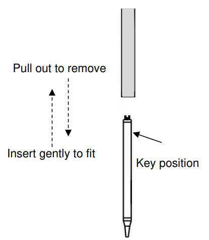
- Make sure to turn the power off and let the iron cartridge cool down. Pull down on the iron cartridge to remove.
If it does not come out, use a silicone tube to pull it down using “some force”. - To insert the new iron cartridge, insert gently until it reaches the end of the cartridge tube. Turn it until you feel the key drop or click into position. When you feel it click, insert it firmly.
*Do NOT insert the iron while the key is in the incorrect position or the key is damaged.
- Slip the silicon ring over the iron cartridge until it comes directly under the holder.
![]() Caution
Caution
- Make sure to turn the power off and let the iron cartridge cool down.
- Carry out “Auto Tuning” after replacing the iron cartridge.
- Make sure that the displayed temperature on the temperature controller and the temperature measured by the tip thermometer are matched after replacing the iron cartridge.
- If the silicon ring is not attached properly, it may cause ignition.
Consumable Parts List
| Image | Type | Description | Remarks |
|
|
Iron cartridge | ||
|
|
TAL*.*-***S60 | Solder tube set for point/slide | |
|
|
RING | Silicone Ring (pkt. of 10 pcs) | |
|
|
125M-601 | Fan Filter for OMEGA (pkt. of 5 pcs) |
It is recommended to replace this filter every 500 operating hours, but please adjust the replace period according to your usage condition and usage environment. |
|
|
ZSB-1001-40T | Roulette blade for Φ0.6~1.6 (40 teeth) | |
|
|
ZSB-1001-80T |
Roulette blade for Φ0.4~0.5 (80 teeth) |
![]() Apollo Seiko Ltd.
Apollo Seiko Ltd.
2271-7 Jinba, Gotenba-shi,
Shizuoka, Japan 〒412-0047
TEL:+81-(0)550-88-2828
FAX: +81-(0)550-88-2830
E-mail: sales@apolloseiko.co.jp
URL: https://www.apolloseiko.co.jp
Documents / Resources
 |
APOLLO DS3 Soldering Controller [pdf] Instruction Manual DS3 Soldering Controller, DS3, Soldering Controller, Controller |