 S and C 6801 Automatic Switch Control

Product Information
Specifications
- Product Name: S&C 6801 Automatic Switch Control
- Compatibility: Front Panel Retrofit for 5801 Automatic Switch Controls
- Manufacturer: S&C Electric Company
Product Usage Instructions
Safety Information
It is crucial to follow all safety instructions provided in the user manual before installing or operating the 6801 Automatic Switch Control.
Installation
- Ensure that only qualified persons, knowledgeable in the installation, operation, and maintenance of electric distribution equipment, handle the installation process.
- Read and retain the Instruction Sheet 1045-565 for reference.
- Properly apply the front panel retrofit kit following the provided instructions.
Tool List
Make sure to have all the necessary tools listed in the user manual before starting the installation process. These tools are essential for a successful retrofit.
Qualified Persons
Only individuals who are trained and competent in distinguishing live parts from nonlive parts, determining proper approach distances, and using precautionary techniques should handle the equipment installation and operation.
Frequently Asked Questions (FAQ)
- Q: Where can I find the latest version of the publication online?
A: The latest version of the publication is available online in PDF format at sandc.com/en/contact-us/product-literature/. - Q: What should I do if the equipment is not within the specified ratings?
A: The equipment is only intended for a specific application within the provided ratings. If the application does not meet these ratings, do not proceed with the installation or operation to prevent any safety hazards.
Introduction
Qualified Persons
WARNING
Only qualified persons knowledgeable in the installation, operation, and maintenance of overhead and underground electric distribution equipment, along with all associated hazards, may install, operate, and maintain the equipment covered by this publication. A qualified person is someone trained and competent in:
- The skills and techniques necessary to distinguish exposed live parts from nonlive parts of electrical equipment
- The skills and techniques necessary to determine the proper approach distances corresponding to the voltages to which the qualified person will be exposed
- The proper use of special precautionary techniques, personal protective equipment, insulated and shielding materials, and insulated tools for working on or near exposed energized parts of electrical equipment
These instructions are intended only for such qualified persons. They are not intended to be a substitute for adequate training and experience in safety procedures for this type of equipment.
Read this Instruction Sheet
NOTICE
Thoroughly and carefully read this instruction sheet and all materials included in the product’s instruction handbook before installing or operating the 6801 Automatic Switch Control. Become familiar with the Safety Information on page 3 and Safety Precautions on page 4. The latest version of this publication is available online in PDF format at sandc.com/en/contact-us/product-literature/.
Retain this Instruction Sheet Proper Application
This instruction sheet is a permanent part of the 6801 Automatic Switch Control. Designate a location where users can easily retrieve and refer to this publication.
WARNING
The equipment in this publication is only intended for a specific application. The application must be within the ratings furnished for the equipment. Ratings for the 6801 Automatic Switch Control are listed in the ratings table in S&C Specification Bulletin 1045-31.
Safety Information
Understanding Safety-Alert Messages
Several types of safety-alert messages may appear throughout this instruction sheet and on labels and tags attached to the product. Become familiar with these types of messages and the importance of these various signal words:
DANGER
“DANGER” identifies the most serious and immediate hazards that will likely result in serious personal injury or death if instructions, including recommended precautions, are not followed.
WARNING
“WARNING” identifies hazards or unsafe practices that can result in serious personal injury or death if instructions, including recommended precautions, are not followed.
CAUTION
“CAUTION” identifies hazards or unsafe practices that can result in minor personal injury if instructions, including recommended precautions, are not followed.
NOTICE
“NOTICE” identifies important procedures or requirements that can result in product or property damage if instructions are not followed.
Following Safety Instructions
If any portion of this instruction sheet is unclear and assistance is needed, contact the nearest S&C Sales Office or S&C Authorized Distributor. Their telephone numbers are listed on S&C’s website sandc.com, or call the S&C Global Support and Monitoring Center at 1-888-762-1100.
NOTICE
 Read this instruction sheet thoroughly and carefully before installing the 6801 Front Panel Retrofit Kit.
Replacement Instructions and Labels
If additional copies of this instruction sheet are required, contact the nearest S&C Sales Office, S&C Authorized Distributor, S&C Headquarters, or S&C Electric Canada Ltd. It is important that any missing, damaged, or faded labels on the equipment be replaced immediately. Replacement labels are available by contacting the nearest S&C Sales Office, S&C Authorized Distributor, S&C Headquarters, or S&C Electric Canada Ltd.
Safety Precautions
 DANGER
The 5801 Automatic Switch Control line voltage input range is 93 to 276 Vac. Failure to observe the precautions below will result in serious personal injury or death. Some of these precautions may differ from your company’s operating procedures and rules. Where a discrepancy exists, follow your company’s operating procedures and rules.
- QUALIFIED PERSONS. Access to the 5801 Automatic Switch Control must be restricted only to qualified persons. See the “Qualified Persons” section on page 2.
- SAFETY PROCEDURES. Always follow safe operating procedures and rules.
- PERSONAL PROTECTIVE EQUIPMENT. Always use suitable protective equipment, such as rubber gloves, rubber mats, hard hats, safety glasses, and flash clothing, in accordance with safe operating procedures and rules.
- SAFETY LABELS. Do not remove or obscure any of the “DANGER,” “WARNING,” “CAUTION,” or “NOTICE” labels.
- MAINTAINING PROPER CLEARANCE. Always maintain proper clearance from energized components.
Front Panel Retrofit Kit
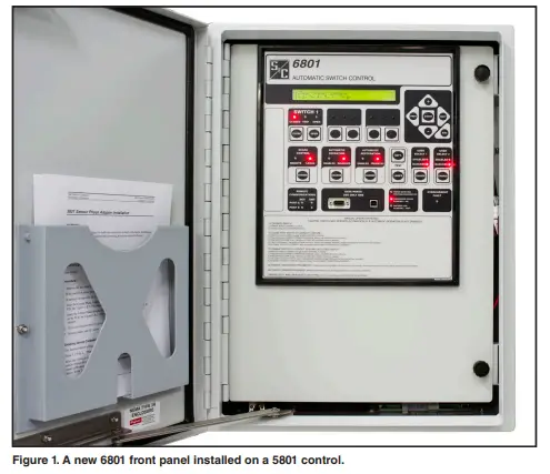
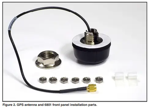
By installing a 6801 Front Panel Retrofit Kit, the 5801 Automatic Switch Control can be converted to a 6801 control. This also adds Ethernet communication capability through an Ethernet port on the back of the panel. The converted 5801 control will be able to operate IntelliTeam® SG Automatic Restoration Software. Figure 1 shows a new 6801 front panel installed on a 5801 control. The 6801 Front Panel with GPS Retrofit Kit includes an antenna to be installed on the enclosure top. Figure 2 on page 6 shows the installation parts supplied with the front panel and the optional GPS antenna.
Field Retrofit Kit
The retrofit kit is available with GPS.
- 6801 Front Panel Retrofit Kit (catalog number 903-002350-01)
- 6801 Front Panel with GPS Retrofit Kit (catalog number 903-002350-02)
Tool List
These tools are required to install the retrofit kit:
- A 11/32-inch nut driver
- A medium Phillips screwdriver
- A 3/4-inch drill bit for metal, only required for GPS Retrofit Kit (catalog number 903- 002350-02)
- An electric drill, only required for GPS Retrofit Kit (catalog number 903-002350-02)
Installation
WARNING
Electric shock hazard. Disconnect ac control power, sensor power, and battery before proceeding. Electric shock can result in serious personal injury or death if instructions, including recommended precautions, are not followed.
Follow these steps to replace the 5801 switch control front panel:
- STEP 1. Disconnect ac control power, and disconnect the battery connector. If the 5801 control has the “-W2” Sensor Power option, disconnect the FIC control cable on the bottom of the enclosure. See Figure 3. All power must be disconnected before beginning Step 2.
- STEP 2. Disconnect all cables attached to the processor on the rear of the front panel, including the X-bus data cable and power connections. See Figure 3 and Figure 11 on page 13.
 STEP 3. If the 5801 control has a Communication option, disconnect the radio harness(es) from the processor and the antenna cable(s) from the radio(s). Remove the six Phillips screws, and remove the Communication option plate from the rear of the front panel. See Figure 3 on page 7.
- STEP 4. Remove the nuts holding the front panel studs to the enclosure hinge. See Figure 4.

- STEP 5. Remove the 5801 control’s front panel. See Figure 5.

- STEP 6. If installing a replacement front panel with the GPS option, install the GPS antenna in the top of the enclosure. Drill a 3/4-inch hole in the enclosure top panel, as indicated in Figure 6. Drill the center of the hole 2 inches (51 mm) from the left side, and 21/2 inches (64 mm) from the front of the enclosure top. See Figures 6 and 7.
NOTICE
Stray metal chips from drilling can cause intermittent mis-operation and damage to electronic components. Take precautions to protect the electronic circuits from chips created while drilling the antenna hole. Put a shop towel under the drilling location.
- STEP 7. Insert the 6801 front panel studs into the hinge holes, and secure the panel with nuts on the second, fourth, and fifth studs from the top. Install the cable clips, one on the top stud and one on the third stud. Install the ground wire on the bottom stud, and tighten all nuts. See Figure 8 and Figure 9 on page 12.

- STEP 8. Skip this step if the GPS option is not included. Insert the GPS antenna into the hole on the enclosure top, and secure it with the antenna nut. Put the antenna cable into the top cable clip, and connect it to the front panel processor, as indicated in Figures 9 and 10 on page 12.


- STEP 9. Insert the power cable into the cable clip at the third nut from the top. See Figure 9 on page 12. Connect power and X-bus data cables to the processor on the front panel, as indicated in Figures 11 and 12.


- STEP 10. Reattach the Communication option plate with the six original Phillips screws. Reconnect the antenna cable(s) to the radio(s). Reconnect the radio harness(es) to the processor. See Figure 13.
- STEP 11. Reconnect the battery, and then ac control power. Reconnect the FIC cable, if removed in Step 1. See Figure 3 on page 7.

Documents / Resources
 |
S and C 6801 Automatic Switch Control [pdf] Installation Guide 6801, 5801, 6801 Automatic Switch Control, 6801, Automatic Switch Control, Switch Control, Control |


