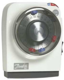
Danfoss GP Programmers and Time Switches
This product complies with the following EC Directives:
- Electro-Magnetic Compatibility Directive.
- (EMC) (2004/108/EC)
- Low Voltage Directive.
- (LVD) (2006/95/EC)
Specifications
- Power Supply: 220/240Vac, 50/Hz
- Switch Action: 1 x SPST, Type 1B
- Switch Rating: 220/240Vac, 50/60Hz, 6(2)A
- Timing Accuracy
- Enclosure Rating: IP20
- Pollution Situation: Degree 2
- Designed to meet BS EN60730-2-7
- Dimensions: 112mm wide, 135mm high, 69mm deep
- Rated Impulse voltage: 2.5kV
- Max. Ambient Temp. : 55°C
- Ball Pressure Test: 75°C
The unit must be installed by a competent electrician, and the installation should conform to I.E.E. Regulations. This unit should be wired via full disconnect by BS EN60730-1, e.g., via a plug and unswitched socket or double pole switch outlet with neon.
Installation Instructions
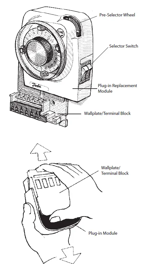
- Loosen the fi xing screw in the base of the unit to release the grey plastic Wiring Cover. Ensure the protective tape over the thumb wheel remains in place.
- Holding the uniclock facece downwards, prefirmlymly in the centre of the wallplate and slide it from the module as shown.
- Fix the Wallplate/Terminal Block to the wall with countersunk No.8 woodscrews or to a steel box to BS 4662. 1970 or a surface mounting steel or moulded box having centres of 23/8″ (60.3mm).
- Referring to the Wiring Diagrams overleaf, connect the unit as shown. Ensure that terminals 3 and 6 are linked where required (Mains Voltage applications) with insulated cable capable of carrying full load current.
- Ensure all dust and debris have been cleared away from the area, then plug the modulfirmlyly into the wallplate, ensuring that the hook at the top of the wallplate engages with the slot at the back of the body. Press the module down until it locates solidly.
- Cut a cable aperture in the Wiring Cover if necessary; replace the Wiring Cover, and tighten the fi xing screw.
- Switch othe n Mains and test for correct operation as follows:
- i) Remove protective tape from the pre-selector wheel.
- ii) Remove the dial cover and rotate the clock dial two complete revolutions to clear the mechanism.
- ii) Check that all positions of the Selector Switch and Tappets operate correctly. (See instructions in User Booklet.)
- Replace the dial cover. Finally,l eave the USER INSTRUCTIONS with the Householder.
- If the unit is to be left turned off and is in a dusty atmosphere, protect the pre-selector wheel by re-affi xing the protective tape.
IMPORTANT: Remove tape before putting unit into service.
Usage Instructions
- Remove protective tape from the pre-selector wheel before use.
- Rotate the clock dial two complete revolutions to clear the mechanism before setting the timer.
- Check that all positions of the Selector Switch and Tappets operate correctly.
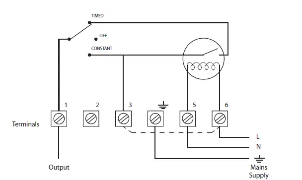
INTERNAL WIRING MODEL 102
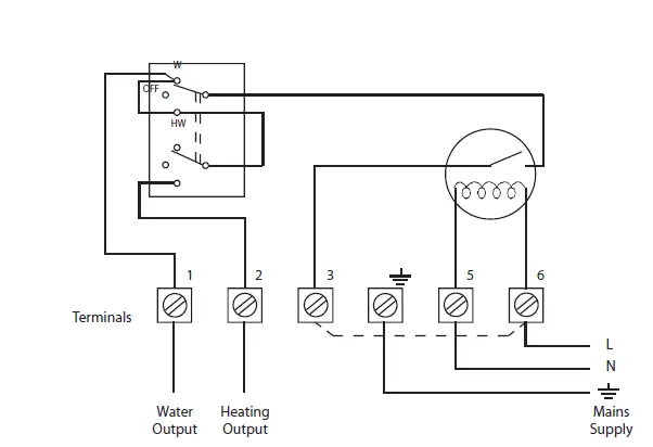
NOTE: Terminals 3 and 6 MUST be linked externally (except when voltage-free switch contacts are required).
TYPICAL EXTERNAL CIRCUITS
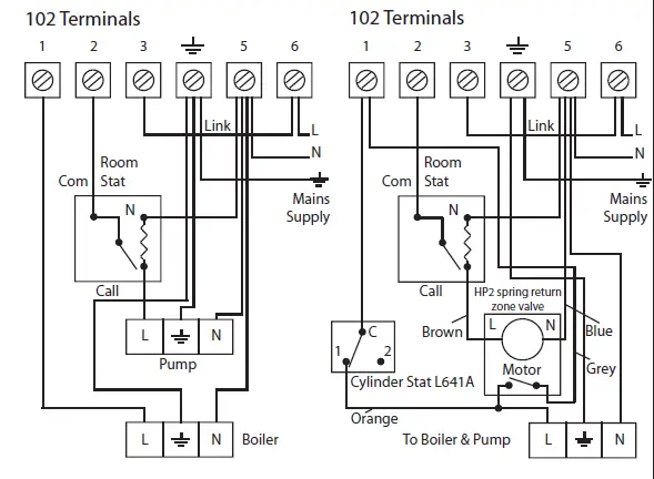
- Typical domestic gas or oil fi red system with gravity hot water and pumped heating. (If a room stat is not required, wire pump L directly to terminal 2 on the 102).
- Fully pumped system with cylinder stat in HW circuit and room stat and 2 port spring return zone valve in heating circuit.
INTERNAL WIRING MODEL 106
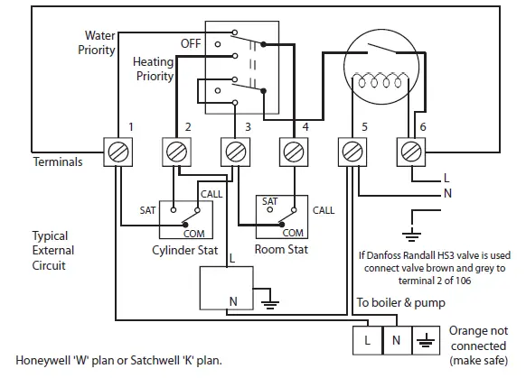
Fully pumped system with 3 port (2 way) diverter valve.
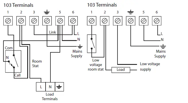
INTERNAL WIRING MODEL 103
NOTE: Terminals 3 and 6 should (in most instances) be linked externally. Exceptions are when control circuits are operating at low voltage (e.g. 24 volts) or for certain Combination Type Boilers (see Boiler Manufacturers Handbook).
TYPICAL EXTERNAL CIRCUITS
- Control of Heating Function Only (Mains Voltage)
Note: If the room thermostat is not required, join timeswitch terminals 1 and 2 with a link suitable for full load current. - Control of Low Voltage Systems (e.g., warm air gas valves, low voltage burners)
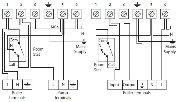
- Typical gas or oil fi red heating system with gravity hot water primary and pumped heating.
- Typical control of heating when used with combination-type boilers.
103 Terminals
NOTE: Ease of installation can be achieved by using the Danfoss Randall Wiring Centre, which is obtainable from most Builders Merchants and Distributors. IF A WIRING CENTRE IS USED, follow the installation instructions included with the unit and not the wiring diagrams shown on this page.
Danfoss Randall can accept no responsibility for possible errors in catalogues, brochures, a nd other printed material. Danfoss Randall reserves the right to alter its products without notice. This also applies to products already on order, provided that such alterations can be made without subsequent changes being necessary in specifications already agreed upon.
- Danfoss Ltd Ampthill Road, Bedford MK42 9ER.
- Telephone: (01234) 364621
- Fax: (01234) 219705
- Email: ukheating@danfoss.com
- Website: www.heating.danfoss.co.uk
FAQs
Q: Can I install this product without professional help?
A: No, the unit must be installed by a competent electrician to ensure safety and compliance with regulations.
Q: What should I do if the unit is not operating correctly?
A: Check the wiring connections and ensure that all steps in the installation and usage instructions have been followed accurately. If issues persist, contact customer support.
Documents / Resources
 |
Danfoss GP Programmers and Time Switches [pdf] Installation Guide 102, 103, 106, GP Programmers and Time Switches, GP, Programmers and Time Switches, and Time Switches, Time Switches |