TERACOM TDO340 Modbus RTU Relay Output Module

FAQs
- Q: What should I do if I need to switch dangerous voltages using the device?
- A: If you need to switch dangerous voltages (over 30V), a skilled person must install the device in rooms with controlled access as per safety guidelines.
Short description
The MODBUS RTU relay output module, model TDO340, is a dependable 4-channel SPST device featuring independent contacts. It fully supports the MODBUS RTU protocol, enabling you to configure relay safety statuses both at startup and in the event of communication loss, ensuring continued system protection. The module is equipped with a watchdog function that detects communication failures and takes prompt action to maintain safety. Additionally, the TDO340 utilizes nonvolatile memory to retain and restore relay states following power outages. This device can be used as a relay output extension for MODBUS RTU master devices.
Features
- RS-485 interface supporting up to 63 nodes
- Non-volatile memory for the relays’ status
- LED indicator for communication status
- Watchdog functionality for communication loss
- Reinforced isolation of relay contacts
- Built-in 120 ohms termination resistor
- DIN rail mounting
- Firmware update via the interface
Applications
- AC/DC consumers commutation;
- Industrial process control;
Specifications
- Physical characteristics
- Dimensions: 52x91x59mm (3-module enclosure)
- Weight: 101g
- Mounting: On 35 mm DIN top-hat rail
- Environmental limits
- Operating temperature range: -20 to 60°C
- Operating relative humidity range: 10 to 90% (non-condensing)
- Storage temperature range: -25 to 65°C
- Storage relative humidity range: 5 to 95% (non-condensing)
- Ingress protection: IP40 (connections IP20)
- Power supply
- Operating voltage range (including -15/+20% according to IEC 62368-1): 5 to 28VDC Current consumption: 130mA@5V
- Relay outputs
- Maximum switching current: 3A
- Maximum switching AC voltage: 250V
- Maximum switching DC voltage: 30V
- Rated load: 3A at 250VAC, resistive, 50k cycles
- 3A at 30VDC, resistive, 30k cycles
- Isolation: 4000 Vrms coil to contact
- 1000 Vrms between open contacts
Caution! If TDO340 is used to switch dangerous voltages (over 30V), a skilled person must install the device in rooms with controlled access.
Interface
- Protocol: Modbus RTU
- Physical layer: RS-485 serial line
- Number of bus transceivers: up to 63
- Bus cable: Twisted, shielded, 2×0.5mm²
- Response time ≤ 50ms
Master response time-out ≥ Response time + Answer time The answer time depends on the number of bits and the baud rate.
- Connectors
- Communication: 3.81mm pitch screwless pluggable for 28 to 16 (AWG) / 0.081 to 1.31 (mm²) wires
- Relay outputs: 5.08mm pitch screwless pluggable for 26 to 14 (AWG) / 0.2 to 1.5 (mm²) wires
- Warranty
- Warranty period: 3 years
Indicators
The status of the device is shown by “Status” LED:
- If the LED blinks every 1 second, the sensor is working properly;
- If the LED blinks every 3 seconds, there is no communication with the controller;
- If the LED does not blink, there is no power supply.
Each relay has a dedicated LED to show its status. A lit LED means the relay is activated (contacts are closed)
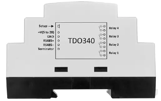
Pinout
- 5-pins connector
- 1 +VDD (5 to 28)
- 2 GND
- 3 RS485+
- 4 RS485-
- 5 Terminator
- 8-pins connector
- 1-2 Relay 1 NO contacts
- 3-4 Relay 2 NO contacts
- 5-6 Relay 3 NO contacts
- 7-8 Relay 4 NO contacts
Installation
According to modbus.org, the “Two-Wire” MODBUS definition states: “A MODBUS solution over a serial line should implement a “Two-Wire” electrical interface in accordance with the EIA/TIA-485 standard. On such a “Two-Wire” topology, only one driver can transmit at any time. Additionally, a third conductor must interconnect all the devices on the bus – the common.”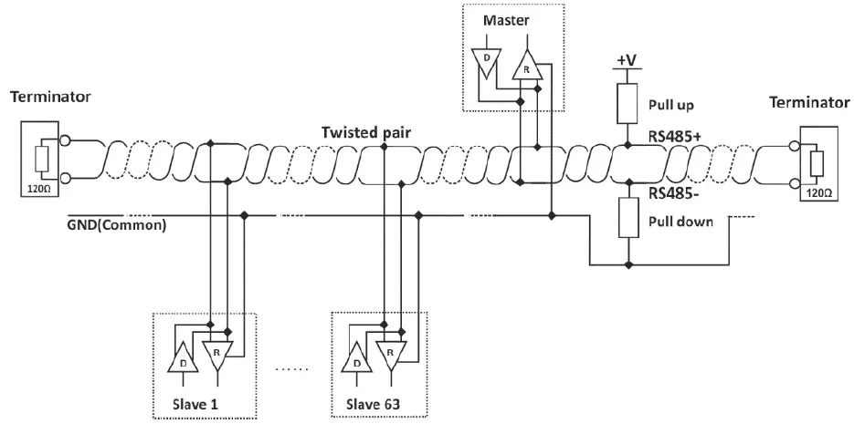
A daisy-chain (linear) topology and UTP/FTP cables are strongly recommended for multiple sensors. For proper operation of the interface, terminators (120 ohms resistors) must be installed at both ends of the bus. The device has a built-in 120-ohm resistor. To terminate the bus, the “RS485-” and “Term” terminals must be shorted.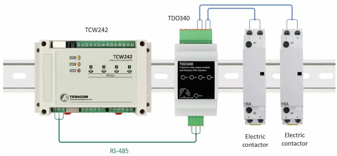
Factory default settings
- Disconnect the power supply.
- Press and hold the “Setup” button.
- While holding the button, connect the power supply.
- The status LED will turn ON for 3 seconds, then flash for 7 seconds, and finally turn ON again.
- Release the button. The device will restart with factory default settings.
Firmware update
- The firmware of the device can be updated by Teracom controller with MODBUS RTU supports or MBRTUUpdate software.
- To put the sensor in update mode, follow these steps:
- Disconnect the sensor from the bus and the power supply.
- Press and hold the “Setup” button. While holding the button, reconnect the power supply.
- The status LED will turn ON for 3 seconds. During these 3 seconds, release the button and press it 3 times to] enter update mode.
- In update mode, the status LED will remain ON permanently.
- Important: The sensor can be updated only if it is the sole device on the bus.
Modbus address table
|
Register name |
R/W |
FC |
Decimal address | Data size |
Default |
Valid values |
|
| PDU | Logical | ||||||
| Holding registers | |||||||
| RS-485 address | R/W | 3, 6, 16 | 10 | 40011 | uint16 | 1 | 1 to 247 |
| Baud rate * | R/W | 3, 6, 16 | 11 | 40012 | uint16 | 19200 | 2400, 4800, 9600, 19200,
38400, 57600 |
| Parity, data, stop bits * | R/W | 3, 6, 16 | 12 | 40013 | uint16 | 1 | 1=E81, 2=O81, 3=N81 |
| Device code | R | 3 | 14 | 40015 | uint16 | 0x00DF | |
| FW version | R | 3 | 15 | 40016 | uint16 | ||
| Vendor URL | R | 3 | 18 | 40019 | 64 bytes UTF-8 |
teracomsystems.com |
|
| Unsigned integer test value | R | 3 | 91 | 40092 | uint16 | 999(0x03E7) | |
| All relay outputs, binary | R/W | 3 | 100 | 40101 | uint16 | 0b0000000000000000
to 0b0000000000001111 |
|
| Relay 1 output, binary | R/W | 3 | 101 | 40102 | uint16 | 0b0000000000000000
to 0b0000000000000001 |
|
| Relay 2 output, binary | R/W | 3 | 102 | 40103 | uint16 | 0b0000000000000000
to 0b0000000000000001 |
|
| Relay 3 output, binary | R/W | 3 | 103 | 40104 | uint16 | 0b0000000000000000
to 0b0000000000000001 |
|
| Relay 4 output, binary | R/W | 3 | 104 | 40105 | uint16 | 0b0000000000000000
to 0b0000000000000001 |
|
| Relays after power on | R/W | 3 | 200 | 40201 | uint16 | 0 | 0 – all relays will return to the last successfully set states
1 – all relays will be activated 2 – all relays will be deactivated 3 – relays will follow settings in registers 201 to 204 |
| Relay 1 after power on | R/W | 3 | 201 | 40202 | uint16 | 0 | 0 – relay will return to the last successfully set state 1 – relay will be activated 2 – relay will be
deactivated |
| Relay 2 after power on | R/W | 3 | 202 | 40203 | uint16 | 0 | 0 – relay will return to the last successfully set state
1 – relay will be activated |
| 2 – relay will be
deactivated |
|||||||
| Relay 3 after power on | R/W | 3 | 203 | 40204 | uint16 | 0 | 0 – relay will return to the last successfully set state 1 – relay will be activated 2 – relay will be
deactivated |
| Relay 4 after power on | R/W | 3 | 204 | 40205 | uint16 | 0 | 0 – relay will return to the last successfully set state 1 – relay will be activated 2 – relay will be
deactivated |
| Relay1 behavior in case of no communication with the device for a period longer than the Timeout (set in register 305) | R/W | 3 | 301 | 40302 | uint16 | 0 | 0 – relay will remain in its last state; no changes
1 – relay will be activated 2 – relay will be deactivated 3 – relay will be switched to the opposite state for the duration set in register 306; The pulse can be used to reset another device. |
| Relay2 behavior in case of no communication with the device for a period longer than the Timeout (set in register 305) | R/W | 3 | 302 | 40303 | uint16 | 0 | 0 – relay will remain in its last state; no changes
1 – relay will be activated 2 – relay will be deactivated 3 – relay will be switched to the opposite state for the duration set in register 306; The pulse can be used to reset another device. |
| Relay3 behavior in case of no communication with the device for a period longer than the Timeout (set in register 305) | R/W | 3 | 303 | 40304 | uint16 | 0 | 0 – relay will remain in its last state; no changes
1 – relay will be activated 2 – the relay will be deactivated 3 – relay will be switched to the opposite state for the duration set in register 306; The pulse can be used to reset another device. |
| Relay4 behavior in case of no communication with the device for a period longer than the Timeout (set in register 305) | R/W | 3 | 304 | 40305 | uint16 | 0 | 0 – relay will remain in its last state; no changes
1 – relay will be activated 2 – relay will be deactivated 3 – relay will be switched to the opposite state for the duration set in register 306; The pulse can be used to reset another device. |
| Timeout of no communication with the device over MODBUS RTU | R/W | 3 | 305 | 40306 | uint16 | 0 | 0 – Infinity communication timeout 1 to 65535 –
timeout in seconds |
| Watch-dog pulse period | R/W | 3 | 306 | 40307 | uint16 | 1 | 1 to 255 – pulse period in
seconds |
| Discrete outputs | |||||||
| Relay 1 | R/W | 1, 5 | 1 | 2 | bit | 0 | 0 or 1 |
| Relay 2 | R/W | 1, 5 | 2 | 3 | bit | 0 | 0 or 1 |
| Relay 3 | R/W | 1, 5 | 3 | 4 | bit | 0 | 0 or 1 |
| Relay 4 | R/W | 1, 5 | 4 | 5 | bit | 0 | 0 or 1 |
- The shown logic decimal addresses are calculated with offsets 1 (discrete outputs) and 40001 (holding registers).
- PDU address – the actual address used in a Modbus Protocol Data unit, transmitted over the bus;
- The settings will take effect after restarting the device by power off, and power on.
Recycling
- Recycle all applicable materials.
- Do not dispose of in the regular household refuse.
MORE INFORMATION
Documents / Resources
 |
TERACOM TDO340 Modbus RTU Relay Output Module [pdf] User Manual TDO340 Modbus RTU Relay Output Module, TDO340, Modbus RTU Relay Output Module, Relay Output Module, Output Module |