myFirstech FTI-STK1 Vehicle Coverage and Preparation Notes
Specifications
- Product Name: FTI-STK1
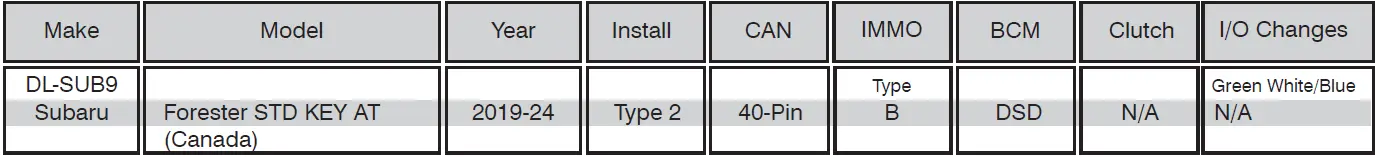
- Vehicle Coverage: Subaru Forester STD KEY AT (Canada) 2019-2024
- Required Accessories: BLADE-AL-SUB9 firmware, Weblink Hub, ACC RFID1
- Connector Type: 40-Pin BCM
Product Usage Instructions
- CAN Connection:
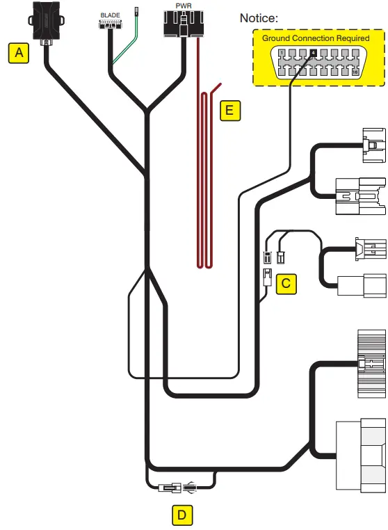
- Type 2 CAN connections are made using the 40-pin BCM connector. Connect the white 2-pin female connector to the black male 2-pin connector at marker [D] of the illustration.
- Immobilizer Connection:
- Type B IMMO requires connecting the black and white 2-pin connectors at marker [C] of the illustration.
- Lights Wiring:
- The FTI-STK1 harness pre-wires parking lights. Replace the green/white wire of the CM I/O connector with the harness’s pre-terminated green/white wire.
- ACC-RFID1 Installation:
- For SUB9 firmware, an ACC-RFID1 is required for remote start as it does not provide immobilizer data. Install ACC-RFID1 before programming the BLADE module to the vehicle.
- 2nd START Output:
- The FTI-STK1 harness includes a pre-wired red/black 2nd START output. If not required in TYPE 2, cut and insulate the provided wire to prevent short circuits when not used.
- I/O Changes:
- No changes are required for I/O connections.
- Additional Advisories:
- Program ACC-RFID1 before programming the BLADE module.
- Secure all 2-pin connections to the main harness body, whether used or unused.
FAQs
- Q: What do the Module LED flashing RED codes indicate during programming?
- A:
- 1x RED = Unable to communicate with RFID or immobilizer data.
- 2x RED = No CAN activity. Check the CAN wire connections.
- 3x RED = No ignition detected. Check the ignition wire connection and CAN.
- 4x RED = Required ignition output diode not detected.
- A:
PRODUCT INFORMATION
- The covered vehicle uses BLADE-AL-SUB9 firmware and the following required accessories, Weblink Hub & ACC RFID1. Flash the module, and update the controller firmware. Please follow the directions for RFID programming before attempting to program the BLADE module to the vehicle.
- CAN: Type 2 CAN connections are made using the 40-Pin BCM connector and require connecting the white 2-pin female connector to the black male 2-pin connector at marker [D] of the illustration.
- Immobilizer: Type B IMMO requires connecting the black and white 2-pin connectors at marker [C] of the illustration.
- Lights: The FTI-STK1 harness pre-wires parking lights. Replace the green/white wire of the CM I/O connector with the harness’s pre-terminated green/white wire.
- ACC-RFID1 (REQUIRED): SUB9 firmware does not provide immobilizer data, an ACC-RFID1 is therefore required for remote start
- 2nd START: The FTI-STK1 harness is pre-wired with a red/black 2nd START output (not required in TYPE 2), cut and insulate the provided wire to prevent short circuits when not used.
- I/O Changes: None required
- Advisory 1: Program ACC-RFID1 before attempting to program the BLADE module to the vehicle.
- Advisory 2: Secure all 2-pin connections, both used and unused, to the main harness body.
- FTI-STK1: Installation and Configuration Notes
- A. REQUIRED ACCESSORY
- B. ADAPTER NOT REQUIRED
- C. REQUIRED CONFIGURATION (TYPE B IMMO)
- D. REQUIRED CONNECTION
- E. NO CONNECTION

FEATURE COVERAGE
| IMMOBILIZER DATA | ARM OEM ALARM | DISARM OEM ALARM | DOOR LOCK | DOOR UNLOCK | PRIORITY UNLOCK | TRUNK/HATCH | TACH OUTPUT | DOOR STATUS | TRUNK STATUS | BRAKE STATUS | E-BRAKE STATUS | A/M ALRM CONTROL | A/M RS CONTROL | AUTOLIGHT CTRL |
- FT-DAS Required for manual transmission.
- BOTH Red & Red/White MUST be connected with the high current application.
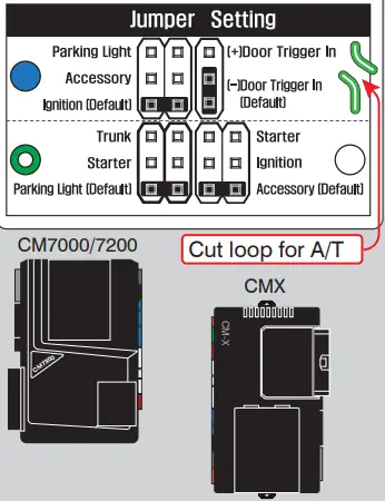
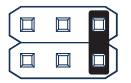
CM900AS/900S Jumper
- START ACC IGN1
Assembly Instruction


LED Programming Error Codes
Module LED flashing RED during programming
- 1x RED = Unable to communicate with RFID or immobilizer data.
- 2x RED = No CAN activity. Check the CAN wire connections.
- 3x RED = No ignition detected. Check the ignition wire connection and CAN.
- 4x RED = Required ignition output diode not detected.
CARTRIDGE INSTALATION
- Slide cartridge into the unit. Notice the button under LED.

- Ready for Module Programming Procedure.
MODULE PROGRAMMING PROCEDURE
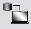
- For this installation, the Weblink HUB is required.

- Remove OEM key 1 from the keychain.

- Place all other keyfobs at least 1 foot away from the Weblink HUB. Failure to comply may result in damage to other keyfobs or interfere with the keyfob reading process.
- Flash the module using the Weblink HUB. Follow the on-screen instructions to complete the keyfob reading process.
- WARNING: Do not press the module programming button. Connect power first. Connect module to vehicle.

- Using OEM key 1, turn the key to the ON position.
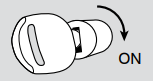
- Wait, the LED will turn solid BLUE for 2 seconds.

- Turn the key to the OFF position.

- Module Programming Procedure completed.
WWW.IDATALINK.COM Automotive Data Solutions Inc. © 2020
Documents / Resources
 |
myFirstech FTI-STK1 Vehicle Coverage and Preparation Notes [pdf] Instruction Manual FTI-STK1-Subaru Forester STD KEY AT-Canada_19-24_ENX, FTI-STK1 Vehicle Coverage and Preparation Notes, FTI-STK1, Vehicle Coverage and Preparation Notes, Coverage and Preparation Notes, Preparation Notes, Notes |
 |
myFirstech FTI-STK1 Vehicle Coverage and Preparation Notes [pdf] Instruction Manual DL-SUB9, CM7000-7200, CM-X, FTI-STK1 Vehicle Coverage and Preparation Notes, FTI-STK1, Vehicle Coverage and Preparation Notes, Coverage and Preparation Notes, Preparation Notes, Notes |
 |
FIRSTECH FTI-STK1 Vehicle Coverage and Preparation [pdf] Installation Guide FTI-STK1 Vehicle Coverage and Preparation, FTI-STK1, Vehicle Coverage and Preparation, Coverage and Preparation |