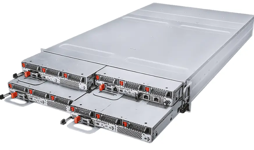
MSI CD270 Multi Node Compute Server
Specifications
- Model: G52-S3862X1
- CPU: CD270-S3071-X2
- Drive Bays: 12 x Hot-Swap 2.5 U.2 Drive Bays (PCIe 5.0 x4, NVMe)
- Memory: Supports DDR5 DIMM slots compatible with RDIMMs, 3DS-RDIMM, and MRDIMMs
CD270-S3071-X2
Server System Quick Start Guide
Descripation
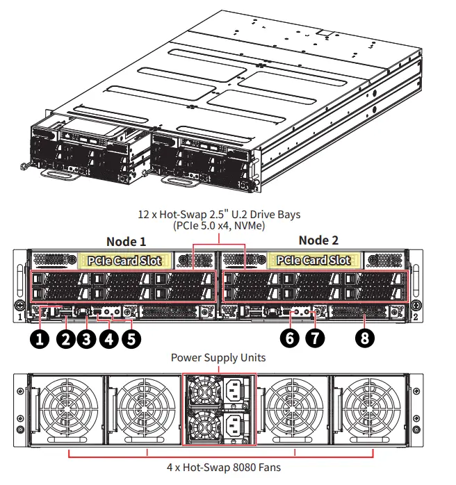
| 1 | COM USB Type-A Port | 5 | System Status LED |
| 2 | USB 2.0 Type-A Port | 6 | UID LED Button (default)/ System Reset Button* |
| 3 | 1000Base-T Ethernet Port (for mgmt.) | 7 | System Power LED Button |
| 4 | Mini-DisplayPort | 8 | OCP 3.0 Mezzanine Card Slot |
* The UID LED button can also function as system reset button, configured using jumper J1_1.
System Node Tray Removal
Important
- Power Off Node First: Removing a powered-on node will cause immediate power loss.
- Independent Power: Each node operates with its own power supply. Turning off one node does not affect others.
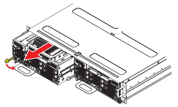
Removal Steps
- Pull the thumb latch aside to release the node.
- Grasp the handle to gently slide the node out of its slot.
Support the weight of the node while removing it to prevent accidental drops.
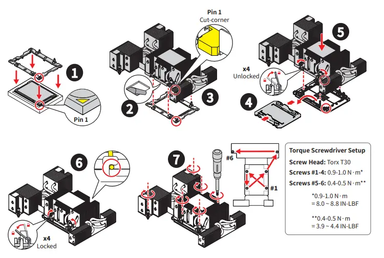
CPU
Single Intel® Xeon® 6900P series processors, TDP up to 500W per node.
CPU and Heatsink Installation
Memory
Each node supports 12 DDR5 DIMM slots, compatible with RDIMMs, 3DS-RDIMM and MRDIMMs
| DIMM Type | Max Frequency | Max Capacity per DIMM |
| RDIMM/ 3DS-RDIMM | 6400 MT/s (1DPC) | 256 GB |
| MRDIMM | 8800 MT/s (1DPC) |
DDR5 Only DIMM Configuration Diagram ( for Intel® Xeon® 6900P Series)
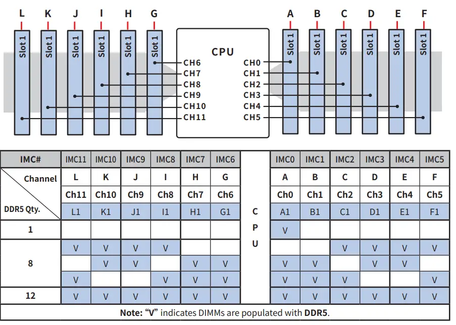
⚠ Important
- There should be at least one DDR5 DIMM per socket.
- DDR5 memory configurations requires same DIMM types, ranks, speeds, and densities.
- Mixing vendors, non-3DS/3DS RDIMMs, 9×4 RDIMMs, or x8/x4 DIMMs is not allowed.
- Mixing DIMMs with different operating frequencies is not validated. When frequencies differ, the system defaults to the lowest common speed.
System Board
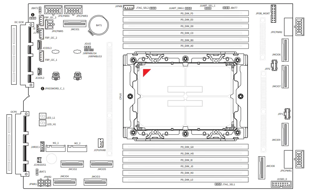
On Board Connectors, Jumpers and LEDs
| Name | Description |
| System Board | |
| JPICPWR_1~4 | 12V PICPWR power connectors (12-pin) |
| JPICPWR_5 | 12V PICPWR power connectors (6-pin) |
| JPWR1~2 | 4-pin power connectors |
| JMCIO1~9 | MCIO 8i connectors (PCIe 5.0 x8) |
| M2_1~2 | M.2 slots (M Key, PCIe 5.0 x2, 2280/ 22110) |
| OCP0 | OCP 3.0 mezzanine slot (PCIe 5.0 x16, NCSI supported) |
| DC-SCM | DC-SCM 2.0 edge slot |
| JCOOL2 | 4-Pin liquid leak detection header |
| JCOOL3 | 6-Pin liquid cooling header |
| JUSB3 | USB 3.2 Gen 1 connector (5 Gbps, for 2 USB ports) |
| JFP1~2 | DC-MHS control panel header |
| JPDB_MGNT | PDB management header |
| JIPMB1 | IPMB header (debug only) |
| JVROC1 | VROC connector (debug only) |
| FBP_I2C_1~3 | I2C headers |
| JCHASSIS1 | Chassis intrusion header |
| JPASSWORD_C_1 | Password clear jumper (default pin 1-2, Normal) |
| JUART_SEL1 | UART BMC/ CPLD select jumper (default pin 1-2, UART BMC to CPU) |
| JTAG_SEL2 | JTAG select jumper (default pin 2-3, BMC to CPU) |
| JBAT1 | MBP/ I3C select jumper (default pin 1-2, MBP) |
| JBAT2 | RTC clear jumper (default pin 1-2, Normal) |
| JBAT7 | PESTI flash select jumper (default pin 2-3, PESTI2 flash) |
| LED_H1, LED_L1 | Port 80 debug LEDs |
| MGT1 DC-SCM Module | |
| TPM | SPI TPM Header (for TPM20-IRS) |
| M2_1 | M.2 Slot (M Key, for ROT1) |
| J_JTAG | Manual programming header (debug only) |
| J3D2 | Force BMC update jumper (default pin 1, Normal) |
| J3C1 | FRU jumper (default pin 2-3, FRU normal operated) |
| J3C5 | JTAG SW jumper (default pin 2-3, JTAG SW enable) |
| J1_1 | ID/ Reset button select jumper (default pin 1-2, ID Button) |
| LED1 | BMC heartbeat LED |
Frequently Asked Questions
- Q: Can I mix different types of DIMMs in this system?
A: No, mixing vendors, non-3DS/3DS RDIMMs, 9×4 RDIMMs, or x8/x4 DIMMs is not allowed. It is recommended to use identical DIMMs for optimal performance. - Q: What is the maximum memory capacity supported per DDR5 DIMM?
A: The maximum capacity supported per DDR5 DIMM is 256 GB.
Documents / Resources
 |
MSI CD270 Multi Node Compute Server [pdf] User Guide X2, S386-S3071-v1.0-QG, G52-S3862X1, CD270 Multi Node Compute Server, CD270, Multi Node Compute Server, Compute Server, Server |