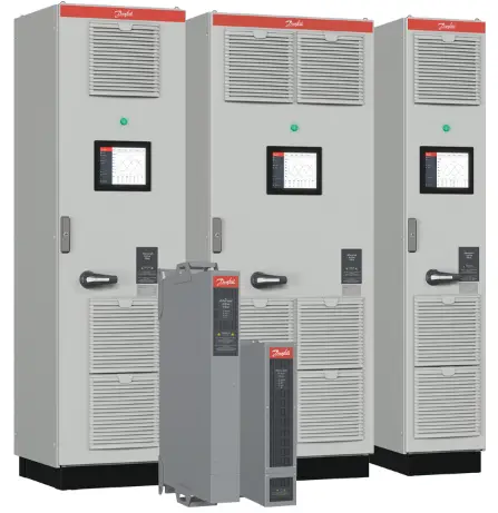
Danfoss AAF007 Advanced Active Filter
Specifications
- Product Name: Advanced Active Filter AAF 007
- Manufacturer: Danfoss
- Model Number: AAF 007
- Voltage: AC mains
- Features: Hazardous voltage protection, DC-link capacitors, automatic start prevention
Product Usage Instructions
1. Installation Safety Instructions
- Overview
Contact Danfoss if you are unclear about any information or if details are missing. - Target Group and Necessary Qualifications
Only qualified personnel should perform installation, start-up, and maintenance. - Safety Symbols
Ensure understanding the safety symbols provided in the manual to prevent hazards. - General Safety Precautions
- Understand the dangers and safety measures in the application.
- Lock out and tag out all power sources before electrical work on the filter.
Instructions
- Safety and Installation Awareness
- Both an installation guide and a safety guide are provided with the filter. Before starting installation, get familiarized with all safety guidelines and precautions in the safety guide.
- The Advanced Active Filter AAF 007 is not intended for service and repair outside the factory. Malfunctioning units must be replaced and returned to the factory.
- Intended Use
The Advanced Active Filter AAF 007 is intended to be used in electrical installations to improve power quality. To achieve improved power quality, the filter injects currents in counter-phase to mitigate distortions on the grid. - Required Tools
- Tape measurer
- Slotted screwdrivers (SL1/SL2)
- PH1, PH2 screwdrivers
- Wrench with extender and 10 mm (for wall mounting)
- Cable strip
- Wire crimper for mains cable
- Electrical and Mechanical Ratings
137G3607 137G3610 Mains supply 3×380–480/277 V / 50–60 Hz 3×380–480/277 V / 50–60 Hz Mains type TN, TT, IT (non-corner grounded) TN, TT, IT (non-corner grounded) Current 0–35 A 0–55 A Ambient temperature Minimum -10 °C (14 °F) Maximum 50 °C (122 °F)
Derating above 40 °C (104 °F)=-3%/K (up to 50 °C (122 °F))
Minimum -10 °C (14 °F) Maximum 50 °C (122 °F)
Derating above 40 °C (104 °F)=-3%/K (up to 50 °C (122 °F))
Ploss 556 W 833 W Weight 16 kg (35.3 lb) 17 kg (37.5 lb) Dimensions (HxWxD) 510x106x360 mm (20.1×4.2×14.2 in) 510x106x360 mm (20.1×4.2×14.2 in) SCCR 5 kA 5 kA - Verifying the Shipment and the Contents
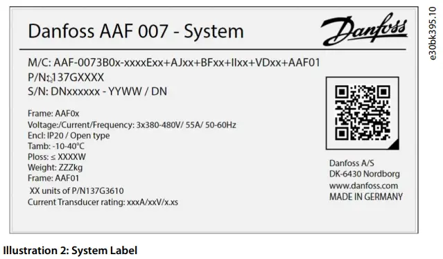
- Ensure that the items supplied and the information on the nameplate correspond to the order confirmation. The filter module label is on the top of each filter module.
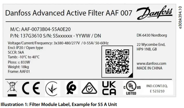
- The nameplate is delivered with the order as a separate item and must be placed on the filter highly visible after installation.
- Ensure that the items supplied and the information on the nameplate correspond to the order confirmation. The filter module label is on the top of each filter module.
Installing the Filter
WARNING: SHOCK HAZARD
Touching hazardous live parts can result in death or serious injury. This IP20/open type filter does not provide protection against direct contact to hazardous live parts. It is intended to be installed inside a supplementary enclosure or in a restricted-access area which provides appropriate protection against electric shock.
NOTICE
- For compliance with EN/IEC 61000-6-8:2020, it is important that the filter is professionally installed and maintained. The professional installer shall evaluate the EMC situation before installation, if the equipment is installed closer than 30 m (98.4 ft) to a residential location.
- This equipment is not intended for use in residential locations and will not guarantee to provide adequate protection to radio reception in such location.
- The IP20/open type filter shall be installed in electrical cabinets or facilities with restricted access only for skilled personnel.
The installation location is important.
- Full output current is available when the following installation conditions are met.
- Maximum surrounding air temperature: 40 ºC (104 ºF), derating 3%/K, maximum 50 °C (122 °F)
- Minimum surrounding air temperature: -10 ºC (14 ºF).
- Thermal conditions: Altitude < 1000 m (3280 ft) above sea level, current derating 5%/1000 m (3280 ft), maximum 4000 m (13123 ft).
- Relative humidity is 5–95% (non-condensing).
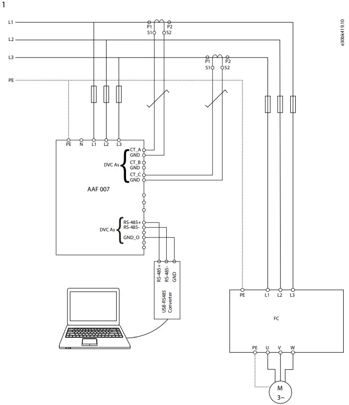
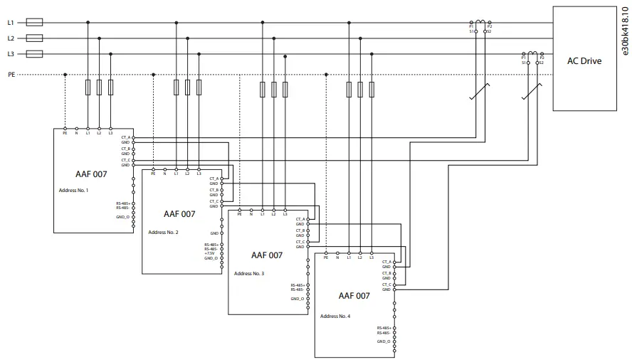
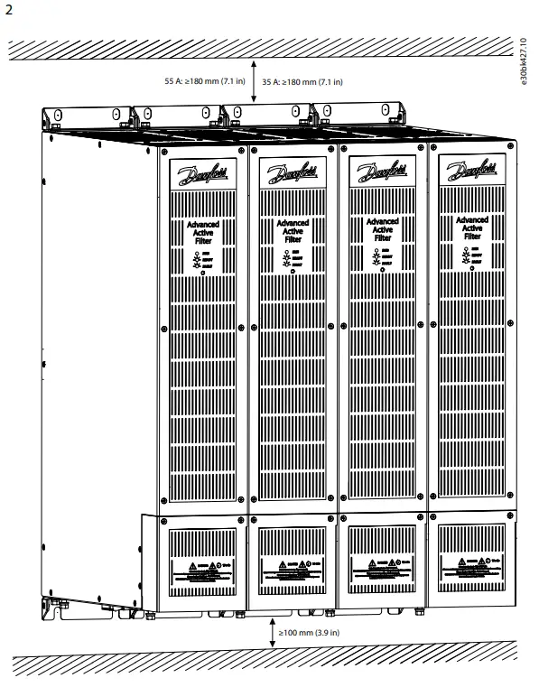
- Step 1 in the Illustrations section shows examples of the entire installation. The lower drawing is an example of a parallel installation of filter modules.
Procedure
- Ensure that the operating environment and electrical installation meet the following conditions.
- Indoor unconditioned/pollution degree 2.
- Overvoltage category 3.
- Not for use in wet locations.
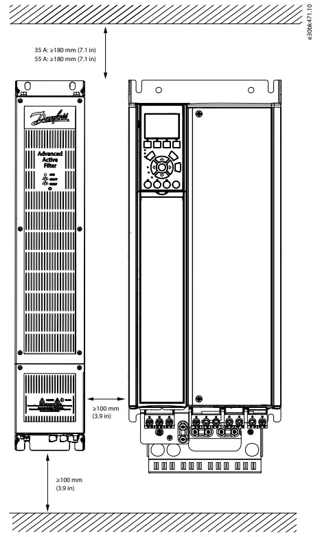
- For correct thermal protection, provide the required clearance above and below the filter.
- Ensure that the current transducer (CT) meets the following requirements described in 1.8 Current Transducers, especially when it has not been ordered with the filter. For correct selection of CT and the according cables, refer to 1.11 Cable and
- Fuse Specifications.
- Install the filter following the numbered steps in the Illustrations section.
- Mount the filter on or against a solid and plain metal surface. Ensure required airflow of 160 m3/h per module for proper cooling. Refer to step 2 in the Illustrations section.
- Install the control wiring.
- Install the current sensor wiring (refer to step 3 in the Illustrations section).
- Install the mains wiring (refer to step 4 in the Illustrations section).
- Securely fasten the mains cover to the filter.
- Ensure correct wiring of the current transducers by:
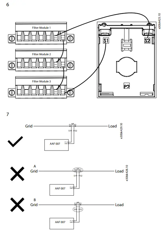
- Checking correct direction/polarity of the CT: P1 towards the point of common coupling.
- Checking correct polarity of CT cables: S1 to CTX and S2 to groundX (refer to step 7 in the Illustrations section).
- Checking correct order of CT to filter terminals: L1:CTA, L2:CTB, L3:CTC. L2:CTB is only required for 4-wire systems with neutral.
- Checking correct sequence of grid phases installation.
- Ensuring the right position of the CT according to the setting in the filter. Load side or grid side.
- Routing of wires: The wires between AAF 007 and the current transformers must be twisted pair cables. A correct function is only possible if the wiring exactly matches the upper diagram in step 7 in the Illustrations section. If wires are interchanged, the harmonics are not to be reduced, but amplified. To avoid interchanging of wires, do not use any wire color twice.
- When the filter is connected to mains, it will start operation. Check that the wiring is correct by assessment of the improvement of the power quality either with the PC tool for filter or with a power quality meter. Consult the operating guide for further information.
Parallel Installation
- It is possible to install the filter modules in parallel to increase the filters’ output current. If filter modules are installed in parallel, 1 CT set could be used for all parallel filter modules. Wire the CT’s secondary wires in series from the CT to filter module 1, to module 2, to module X, and back to the CT terminals S2 or I, see step 1 in the Illustrations section.
- For correct wiring of the current transducer when having 2 filters, refer to step 5 in the Illustrations section.
- For correct wiring of the current transducer when having more than 2 filters, refer to step 6 in the Illustrations section. Ensure that the CT configuration is configured to “series” (default) when applying series connection of CTs as described in steps 5 and 6 in the Illustrations section.
- Refer to step 2 in the Illustrations section for correct clearance distances what ensures correct operation in respect to thermal and electro-magnetic considerations.
Current Transducers
- The Advanced Active Filter AAF 007 needs extra current transducers (CTs). The possible installations of the CTs are on the mains side/closed loop, which measures the mains current, including the filter output current, and on the load side/open loop, which measures just the load current without the filter current.
- On both settings, a CT is required. A CT set consists of 2 CTs. A 3-phase 3-wire system has 3 conductors but just 2 phase currents/
conductors are measured with CTs on phase L1 and phase L3. Phase 2 is calculated internally. If 3 CTs are already existing, only phases L1 and L3 has to be connected to the filter. - If the current transducers are already in the installation or are ordered separately to the filter, ensure that they meet the following specifications to guarantee the expected performance of the filter:
- Minimum burden 2.5 VA
- Minimum accuracy class 0.5
- 5 A secondary current
- The cross-section of the wires has a significant influence on the quality of the control. If the cross-section is too small in relation to the wire length, the resulting measurement will be too small to achieve a good control quality and good reduction of harmonics. A = 2 × d × v × I2 × ρ/ S
- The following values need to be known:
- S = Power of the current transformer (typically 2.5 VA)
- d = Distance (length of cableway) between filter and current transformer
- v = Twisting factor (typically 1.5)
- I = Secondary current of the current transformer (typically 5 A)
- ρ = Rho = Specific resistance of copper (0.01786 Ω×mm2/m )
Example: = 2 × 2m× 1 . 5 × 52 × 0 . 01786 Ω×m/2 . 5 VA ×mm2 = 1 . 07 mm2
Four-wire System
- All descriptions in the previous sections and following illustrations are targeting 3-wire systems. The filter can also operate in 4-wire systems. Additional to the steps already described and illustrated, the following must be done:
- A 3rd CT must be installed on phase 2/phase B. The Neutral wire must be connected to the mains terminal. In the PC tool for the filter, adjust the grid topology to 3P4W.
NOTICE
FILTER MALFUNCTION
- Connecting the neutral wire in 3-wire applications will cause the filter to work improperly.
- Do not connect the neutral wire in 3-wire applications.
Power Losses and Efficiency
For power loss data including part load losses, see https://ecosmart.mydrive.danfoss.com.
Cable and Fuse Specifications
The filter is protected internally with semiconductor fuses. Branch protection is subject to local installation conditions and regulations, and thus no recommendations can be made. To support selection of suitable branch protection, the internal fuses of the filter are specified in the following table.
| 35 A module | 55 A module | |
| L1/L2/L3 cross-section | Rigid: 2.5–35 mm2 (2 AWG)
Flexible: 2.5–25 mm2 (14–4 AWG) Flexible with ferrule: 2.5–25 mm2 (14–4 AWG) |
Rigid: 2.5–35 mm2 (2 AWG)
Flexible: 2.5–25 mm2 (14–4 AWG) Flexible with ferrule: 2.5–25 mm2 (14–4 AWG) |
| Maximum stripping | 18 mm (0.7 in) | 18 mm (0.7 in) |
| Torque | 2.5–3.0 Nm (22.12–26.5 in-lb) | 2.5–3.0 Nm (22.12–26.5 in-lb) |
| Material | Copper | Copper |
| Temperature rating | 70 °C (158 °F) | 70 °C (158 °F) |
| PE cross-section | 16 mm2 (6 AWG) | 16 mm2 (6 AWG) |
| Maximum stripping | 18 mm (0.7 in) | 18 mm (0.7 in) |
| Cable lug | O-type 5–6 mm | O-type 5–6 mm |
| Torque | 2.5–3.0 Nm (22.12–26.5 in-lb) | 2.5–3.0 Nm (22.12–26.5 in-lb) |
| Material | Copper | Copper |
| Temperature rating | 70 °C (158 °F) | 70 °C (158 °F) |
| CT cables cross-section | 2.5 mm2 (14 AWG) | 2.5 mm2 (14 AWG) |
| Torque | 0.8 Nm (7.1 in-lb) | 0.8 Nm (7.1 in-lb) |
| Control cables cross-section | 1 mm2 (17 AWG) | 1 mm2 (17 AWG) |
| 35 A module | 55 A module | |
| Torque | 0.8 Nm (7.1 in-lb) | 0.8 Nm (7.1 in-lb) |
| Internal semiconductor fuse | Sinofuse RS308-HB-4G100A 750VDC | Sinofuse RS308-HB-4G100A 750VDC |
llustrations


EU DECLARATION OF CONFORMITY
Danfoss A/S
Danfoss Drives declares under our sole responsibility that the
- Product category: Filters
- Type designation(s): 137G3610
Covered by this declaration is in conformity with the following directive(s), standard(s) or other normative document(s), provided that the product is used in accordance with our instructions.
Low Voltage Directive 2014/35/EU
EN 62477-1:2012/A1:2017 Safety requirements for power electronic converter systems and equipment – Part 1: General
EMC Directive 2014/30/EU
- EN 61800-3:2018 Adjustable speed electrical power drive systems – Part 3: EMC requirements and specific test methods. EN IEC 61000-3 -2 :2019-12 Electromagnetic compatibility (EMC) – Part 3-2: Limits – Limits for
- harmonic current emissions (not applicable due to the fact that this product is reducing the harmonic current emission )
- EN IEC 61000-3 -3 :2020-07 Electromagnetic compatibility (EMC) – Part 3-3: Limits – Limitation of voltage changes, voltage fluctuations and flicker in public low-voltage supply systems, for equipment with rated current ≤16 A per phase and not subject to conditional connection (representative for units >16A)
- EN IEC 61000-6 -2 :2019-11 Electromagnetic compatibility (EMC) – Part 6-2: Generic standards – Immunity standard for industrial environments
- EN IEC 61000-6-4 :2020-09 Electromagnetic compatibility (EMC) — Part 6-4: Generic standards –
- Emission standard for industrial environments
RoHS Directive 2011/65/EU including amendment 2015/863
EN63000: 2018 Technical documentation for the assessment of electrical and electronic products with respect to the restriction of hazardous substances
Classified as Business
Danfoss only vouches for the correctness of the English version of this declaration. In the event of the declaration being translated into any other language, the translator concerned shall be liable for the correctness of the translation
- ID No: 00777534
- This doc. is managed by 500B0577
- Revision No: A,2
- DocuSign Envelope ID: 607DDAA3-CBE7-4509-B28A-A9ACB8CD01FD
declares under our sole responsibility that the
- Product category: Filters
Type designation(s): 137G3610
Covered by this declaration is in conformity with the following directive(s), standard(s) or other normative document(s), provided that the product is used in accordance with our instructions.
- Electrical Equipment (Safety) Regulations 2016
BS EN 62477-1:2012/A1:2017 Safety requirements for power electronic converter systems and equipment – Part 1: General - Electromagnetic Compability Regulations 2016
- BS EN 61800-3:2018 Adjustable speed electrical power drive systems – Part 3: EMC requirements and specific test methods.
- BS EN IEC 61000-3 -2 :2019-12 Electromagnetic compatibility (EMC) – Part 3-2: Limits – Limits for harmonic current emissions (not applicable due to the fact that this product is reducing the harmonic current emission )
- BS EN IEC 61000-3 -3 :2020-07 Electromagnetic compatibility (EMC) – Part 3-3: Limits – Limitation of voltage changes, voltage fluctuations and flicker in public low-voltage supply systems, for equipment with rated current ≤16 A per phase and not subject to conditional connection (representative for units >16A)
- BS EN IEC 61000-6 -2 :2019-11 Electromagnetic compatibility (EMC) – Part 6-2: Generic standards –
- ~Immunity standard for industrial environments
- BS EN IEC 61000-6-4 :2020-09 Electromagnetic compatibility (EMC) — Part 6-4: Generic standards –
- Emission standard for industrial environments
- The restriction of the Use of Certain Hazardous Substances in Electrical and Electronic Equipment
- Regulations 2012 as amended
- BS EN63000:2018 Technical documentation for the assessment of electrical and electronic products with respect to the restriction of hazardous substances
Classified as Business
Danfoss only vouches for the correctness of the English version of this declaration. In the event of the declaration being translated into any other language, the translator concerned shall be liable for the correctness of the translation
- ID No: 00777534
- This doc. is managed by 500B0577
- Revision No: A,2
Danfoss A/S
Ulsnaes 1 DK-6300 Graasten vlt-drives.danfoss.com
Danfoss can accept no responsibility for possible errors in catalogs, brochures, and other printed material. Danfoss reserves the right to alter its products without notice. This also applies to products already on order provided that such alterations can be made without subsequential changes being necessary in specifications already agreed. All trademarks in this material are property of the respective companies. Danfoss and the Danfoss logotype are trademarks of Danfoss A/S. All rights reserved.
FAQ
Q: How can I prevent automatic start of the filter?
A: To prevent automatic start-up, ensure the EPO contact jumper is in place, all covers are mounted securely, current transducers are correctly installed, and consider disabling automatic connection via PC software. Disconnect the filter from mains when necessary.
Q: What should I do in case of internal failure in the drive?
A: Ensure all safety covers are in place and properly fastened before applying power to prevent any internal failure hazard that could result in serious injury.
Documents / Resources
 |
Danfoss AAF007 Advanced Active Filter [pdf] User Guide AAF007, AAF007 Advanced Active Filter, AAF007, Advanced Active Filter, Active Filter, Filter |