HaoruTech RTLS1 Positioning Module
Specifications:
- Product Name: HR-RTLS1-PDOA
- Manufacturer: Haorutech co. Ltd
Product Information:
HR-RTLS1-PDOA is a high-precision real-time positioning system developed by HR Technology. It supports two positioning modes: Time of Flight (TOF) and Phase Difference of Arrival (PDOA) angle measurement. The system can be used in following mode or single anchor positioning mode, making it versatile for various location application scenarios.
System Features:
- High-precision positioning
- Supports TOF and PDOA angle measurement
- Versatile for different application scenarios
Product Superiority:
| Comparing Items | HR-RTLS1-PDOA | Other products |
|---|---|---|
| Core chip | Based on the latest DW3220 | Based on the traditional single chip solution, the first inDW1000 |
Product Usage Instructions
System Deployment:
Equipment Preparation:
Ensure all components are present and in working condition.
PDOA Anchor Installation:
Mount the PDOA anchors securely in desired locations.
Tag Installation:
Attach tags to objects or individuals that require tracking.
Driver Installation:
Install necessary drivers on the system for proper functionality.
Connect To PC Software:
Establish connection with the PC software for data processing.
Anchor Calibration:
On Board OLED Display:
Calibrate anchors using the onboard OLED display for accurate positioning.
Introduction
HR-RTLS1-PDOA is a high-precision real-time positioning system(based on DW3000 series chips of Decawave company) developed by HR Technology.
HR-RTLS1-PDOA supports two positioning mode: TOF and PDOA Angle measurement. It can be applied as a following system or single anchor positioning mode. By different module combinations, it can adapt to most location application scenarios.
System features
Popular MCU-STM32, friendly to beginners:
The ULM1/ULM3/LD150 module of HR-RTLS1 takes STM32F103CBT6 series (or fully compatible alternative chip made in China) as the main control MCU.
The wearable devices take STM32L151CBU6 low-power microcontroller, which is conTabled by CUBEmx tool, developed by HAL library and KEIL-MDK integrated development environment.
Easy extended interface:
Modules provide external expansion data interfaces, which can be easily connected to PC, mobile phone, other microcontroller, Raspberry PI, Arduino, PLC and other devices for expansion and development.
High positioning accuracy:
The system takes Decawave high-precision positioning IC as the core positioning module. It works with self-developed positioning algorithm and filtering algorithm, which makes the positioning tag adapting to various complicated field conditions. The positioning accuracy is 10cm (CEP95);
Support multi-tags and multi-anchors:
The system can eaisly expands the number of anchors and tags by configuration, which is convenient for users to expand the system;
Built-in Kalman filter algorithm in module
The built-in Kalman filter algorithm can be turned on/off to make the output data stable and smooth.
Product Superiority
Table 3-1 RTLS1-PDOA Product Superiority
| Comparing Items | HaoruUWB | Other products |
| Core chip | Based on the latest DW3220
single chip solution, the first in the industry. |
Based on the traditional
DW1000 dual-chip solution. |
| On-board components of
anchors. |
Less components, easy to be integrated. | More components, hard to be integrated. |
| Overall cost | Less | Higher |
|
Power Consumption |
It only uses 10% of the power
consumption of the traditional dual DW1000 chip. |
High |
| Whether compatible with TWR multi-
anchor positioning |
Yes, PDOA anchor can also be used as a trilateral positioning
anchor |
No, PDOA anchor can only complete its own function. |
Series Products
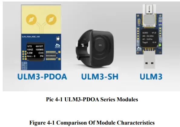
| 序号 | 型号 Model | 主要特点 Main Characteristics |
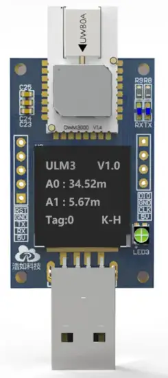
| 1 | ULM3 | Official DWM3000 modules, displayer, 40 meters |
| 2 | ULM3-SH | Bracelet shell, built-in battery, motion detection, 40
meters |
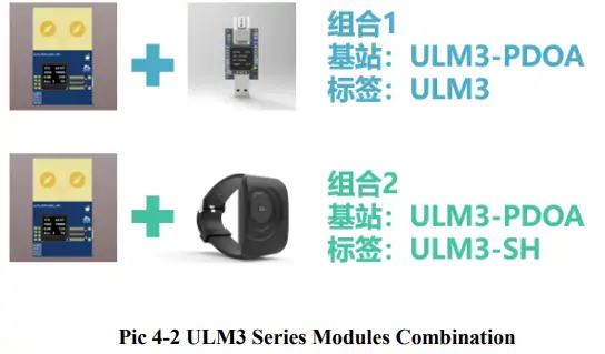
| 3 | ULM3-PDOA | PDOA anchors, angle measuring, single anchor positioning, following vehicle, 40 meters. |
As showing in below picture, HR-RTLS1 series modules
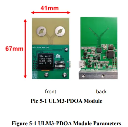
System Parameters
ULM3-PDOA Parameters
| Category | Parameter |
| Power | DC5V external power supply |
| Maximum Detection Range | 40m (open area) @6.8Mbps |
| MCU | STM32F103CBT6 (GD32F103CBT6) |
| Display Onboard | 0.6 inch OLED |
| Module Size | 41*67.5mm |
| Ranging Accuracy | ±5cm |
| Detect Angle | 120°(centralized by the module, -60°
~+60°) |
| Angle Accuracy | ±5 |
| Working Temperature | -20~70℃ |
| Communication Mode | USB to serial port / TTL serial |
| Data Update Frequency | 100Hz (MAX, adjustable) |
| Frequency Domain | 6250-8250MHz (CH5/CH9) |
| Bandwidth | 500MHz |
| Type of Antenna | PCB double antenna |
| Emission power spectral density
(Programmable) |
-41dBm/MHz |
| Communication Rate | 6.8Mbps |
ULM3 Parameters
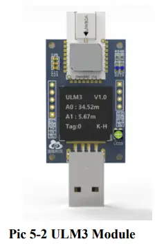
Table 5-2 ULM3 Module Parameters
| Category | Parameter |
|
Power |
DC3.7V~5V external power supply
(power bank or li-ion battery) |
| Maximum Detection Range | 40m (open area) @6.8Mbps |
| MCU | STM32F103CBT6 (GD32F103CBT6) |
| Display Onboard | 0.6inch OLED |
| Module Size | 27*70mm (include antenna and base) |
| Ranging Accuracy | ±5cm |
| Working Temperature | -20~70℃ |
| Communication Mode | USB to serial port / TTL serial |
| Data Update Frequency | 100Hz (MAX, adjustable) |
| Frequency Domain | 6250-8250MHz (CH5/CH9) |
| Bandwidth | 500MHz |
| Type of Antenna | Onboard ceramic antenna |
| Emission power spectral density
(Programmable) |
-41dBm/MHz |
| Communication Rate | 6.8Mbps |
System Application
- Small range positioning of single anchor;
- Following luggage, tool car and other following systems;
- Anti-loss tag, airtag, etc.;
- One finger pointing connection application;
System Deployment
Equipment Preparation
- ULM3-PDOA module, some ULM3 tags( or ULM3-mini wristband-tags), 1 microUSB cable, 1 anchor holder.
| List
Number |
Component Name |
| 1 | 1 ULM3-PDOA module |
| 2 | ULM3 tags( or ULM3-mini wristband-tags) as many as
needed |
| 3 | 1 power bank matches ULM3 tag for power supply. |
| 4 | 1 microUSB cable |
| 5 | 1 Anchor holder, 4 M3 screws,2 copper pillar. |
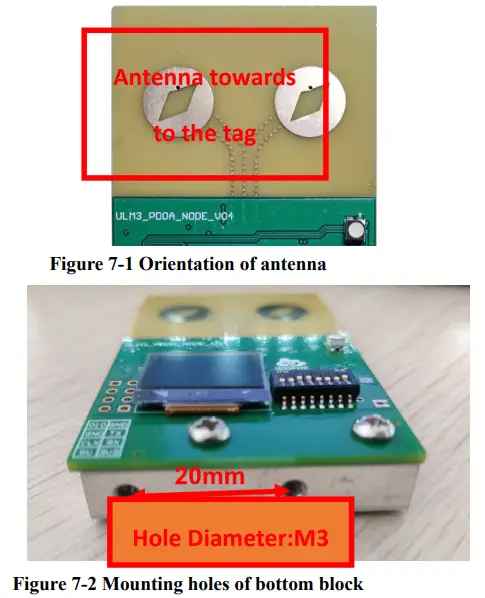
PDOA Anchor Installation
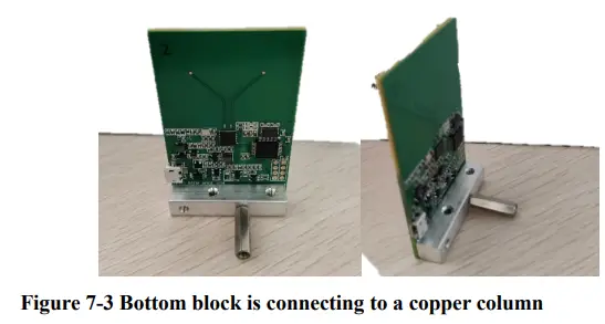
The antenna of ULM3-PDOA module is oriented towards the positioning tag. The module is powered by an external 5V power supply. There is a square block fixed on the bottom of the module, which can be fixed on the UGV or the desktop with M3 screws. Also, it can be connected to a copper column to increase the supporting force to placed on the horizontal platform.
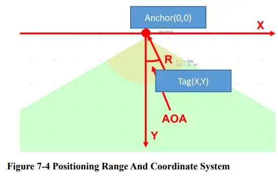
The anchor was set as the coordinate point (0,0) to establish the coordinate system, and the Y axis was directly in front of the anchor. The tag positioning and AOA calculation could be completed from -60°to +60°.
Matters need attention:
- The tag should be positioned within the correct coverage range of anchor, otherwise there may occur some errors, such as inaccurate positioning;
- The antenna surface of anchor should be orientated towards the tag;
- The distance between the anchor and the tag should be greater than 1 meter;
- The anchor should be installed in an open area;
- There should be no occlusion between the tag and the anchor, especially no steel plates and other metals.
Tag Installation
There is a USB interface at the bottom of the ULM3 tag, which should be connected to the charging bank,supplied with the goods, for power supply. The ULM3-mini bracelet tag has built-in battery, long pressing the SOS button for 3 seconds to power it up.
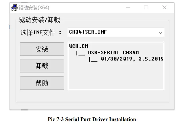
Driver Installation
Go to“HR-RTLS1-PDOA 开箱测试资料\串口驱动”catalogue,double click CH341SER.EXE to install it,use the default settings,click “install” button,follow the prompts to finish install process.
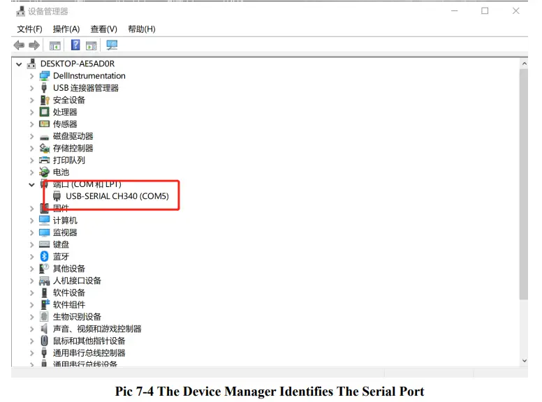
After the driver is installed, connect the anchor/tag module to the computer. Open the device manager on the computer and check if the serial port driver is installed properly. If the port is identified, record the serial port number of CH340. For example, the following picture shows that the driver is installed, the device is identified, and the serial port number is COM5. If the serial port is not displayed or there is “!” exclamation mark error, please contact the corresponding after-sales engineers.
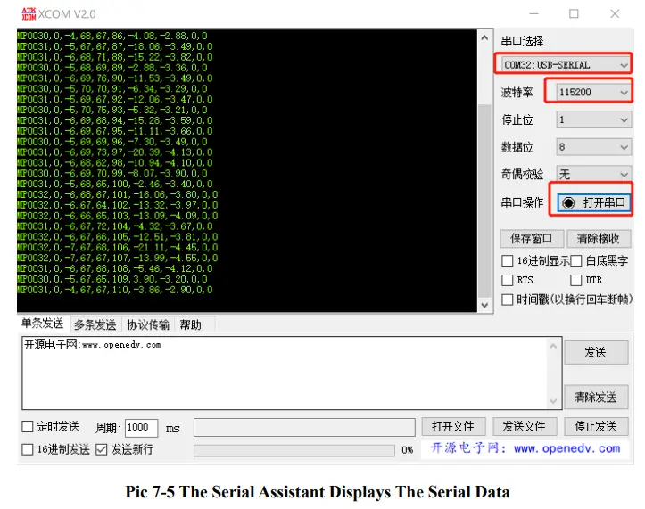
Go to“HR-RTLS1-PDOA 开箱测试资料\串口驱动”catalog, double click XCOM V2.0.exe to run the Serial port debugging assistant,select the serial port number identified,set baud rate to 115200, click “打开串口”。
Run tag module, if the message box can receive string data beginning with MP, it means that the serial port data communication is working and the anchor is successfully connected to the computer.
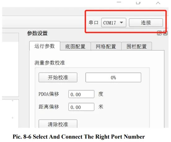
Connect To PC Software
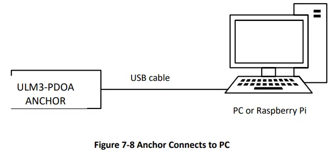
Open “HR-RTLS1-PDOA 开箱测试资料\ 上位机软件”catalog ,unzip “HR_PDOA_RTLS.zip”,run HR_PDOA_RTLS.exe,now we can run PC software. Select the correct serial port number in the upper right corner of the software, click “Connect”。
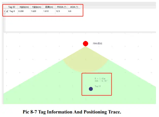
After connecting to the PC and switch on the tag successfully, the PC software can display the tag information and positioning trace.
Communication protocol
Uplink data protocol
The uplink data protocol is the data uploaded actively by the UWB module through the serial port.
Serial communication baud rate: 115200bps-8-n-1
Communication protocol:
MPxxxx,tag_id,x_cm,y_cm,distance_cm,RangeNumber,pdoa_deg,aoa_deg,distan ce_offset_cm,pdoa_offset_deg\r\n
Serial communication data example: MP0036,0,302,109,287,23,134.2,23.4,23,56
Table 8-1 Serial Communication Protocol Description
| Content | Example | Description |
| MPxxxx | MP0036 | Head of the data packet, 0036 is the number of all data bytes except MPxxxx, including the ending \r\n, which is fixed to 4 characters. If it is
less than the length, fill up with 0. |
| tag_id | 0 | The current tag ID |
| x_cm | 302 | X coordinates of the tag, integers,
units:cm |
| y_cm | 109 | Y coordinates of the tag, integers,
units:cm |
| distance_cm | 287 | Direct distance between the anchor
and the tag, integers, units:cm |
| RangeNumber | 23 | Serial number of ranging,0-255 |
| pdoa_deg | 134.2 | PDOA value, Float, units:degree |
| aoa_deg | 23.4 | AOA value, Float, units:degree |
| distance_offset_cm | 23 | Calibration value of direct distance
between the anchor and the tag, integers, units:cm |
| pdoa_offset_deg | 56 | Calibration value of PDOA value,
Float, units:degree |
| \r\n | Ending data |
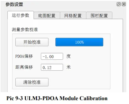
Anchor Calibration
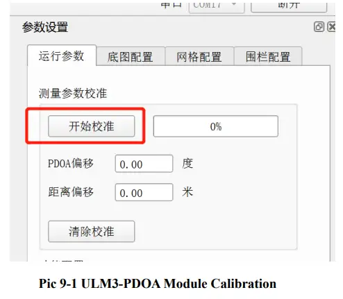
Due to the influence of welding, PCB manufacturing process and other factors, the RF transmission line of the two antennas of the ULM3-PDOA module will cause small errors, resulting in PDOA Angle deviation, which can be calibrated by the PC software.
After the ULM3-PDOA module is successfully connected to PC and the tag location data is displayed, click the “Start calibration” button, place the anchor and tag at the same height as prompted, place the tag in front of the two antenna centers of the anchor, and measure the distance between the anchor and tag. It is recommended that the distance should be more than 2 meters.
Fill the measured distance value into the PC software, and keep the position of the tag and anchor unchanged until the calibration progress bar rolls to 100%, which is when the calibration is completed.
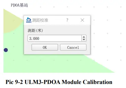
After the calibration is completed, the PC software prompts the calibration deviation, and the anchor will output calibration data according to this deviation. If you need to clear the calibration data, you can click the “Clear calibration” button to reset the deviation value and re-calibrate.
On Board OLED Display
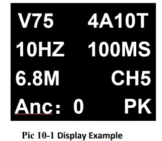
Figure 10-1 Display Information Description
| Example | Description |
| V75 | Firmware Version |
| 4A10T | Maximum 4 anchors and 10 tags |
| 10HZ | Data update rate(current mode) |
| 100ms | Current data update period(=1/ Data
update rate) |
| 6.8M | Current UWB air rate is 6.8Mbps(Alternative option: 110k) |
| CH5 | Current UWB channel is CH5(Alternative
option: CH2 Channel 2) |
| Anc:0 | Current module is anchor, ID=0
(Alternative option: Tag) |
| K | Kalman filtering is enabled (no display:
disabled) |
Development and learning files
List of development and learning materials we provide after purchasing:
Table 10-1 Documents
| No. | Category | File type |
| 1 | Quick guide of QT software | |
| 2 | RTLS1-PDOA Bilateral ranging
agreement |
|
| 3 | ULM3-PDOA_UserManual | |
| 4 | RTLS1-PDOA _UserManual | |
| 5 | DW3000 UserManual by Qorvo | ZIP |
FAQ
Is the system open source?
The system is completely open sourced, including embedded code, upper computer code, algorithm and etc. Besides, it provides related development manuals and video tutorials, which helps the user to begin secondary development easily.
Is the system mature? Does it need redeveloping before use?
The system is already mature, it provides complete positioning function, which means the user can get positioning data through ports directly. Also, users can redevelop the system to meet their own needs through editing source code.
How many modules do I need?
It depends. Here are some examples:
- If you need to range from one to one, it needs two.
- If you need to set up 2D position, it needs 4, which includes 3 anchors and 1 tag.
- If you need to set up 3D position, it needs 5 at least, which includes 4 anchors and 1 tag.
- If you already had modules in hand and want to increase the number of anchors or tags, you need to buy related numbers of the missing modules.
- If you need to position 10 tags, then you need to get 4 anchors and 10 tags, which results in 14 modules.
We recommend buying 5 modules at least, for the following reasons:- 4 anchors positioning can cover two times the area than 3 anchors positioning.
- There always some communication failure during the testing; for 4 anchors positioning method, it will finish the positioning by 3 anchors data out of 4, but for 3 anchors positioning method, it needs to finish the positioning by all 3 anchors data, which leads to reduce the success rate.
- Also, 4 anchors & 1 tag can be reset to 3 anchors & 2 tags as well.
What is the positioning accuracy? Is the accuracy related to the area?
For XY positioning, the accuracy is 10cm (CEP95); for Z direction, the accuracy is 30cm (CEP95). There is no direct relationship between usage area and accuracy. There is no reducing accuracy when increase the usage area. But it should be noted that for the large power needed for ULM1-LD600, it will have an obvious multipath effect when use in 5*5cm area, so we recommend using it in a larger area.
Does the module have shell? Is it waterproof?
ULM1 does not have shell, LD150/LD600 have shell and external antenna. But the shell is not either sealed or waterproof.
How long is the battery standby time?
It depends on the external power supply capacity and emission frequency. For ULM1 equipped with matching power supply, the anchor standby time is approx. 10 hours, and the tag standby time is approx. 12 hours.
What the difference between RTLS1, RTLS2, RTLS3?
RTLS1, RTLS2, RTLS3 are the third generation UWB positioning product that developed by our company.
- RTLS1 is based on the STM32 platform development kit, open source and available by two types:50m and 600m. It is suit for study assessment, study UWB underlying drive method, product source code migration, system integration and etc.
- RTLS2 is productized equipment, closed source, communicate by ethernet, WEB interface. It is suit for application directly in the project.
- RTLS3 is based on Arduino platform development kit, open source, the underlying drive is encapsulated and easy to redevelop. It is suit for study assessment, development research, project study in college, system integration and etc.
What is the update frequency for the tag?
The default frequency is 112ms, it can set to 10ms(6.8Mhz) for minimum duration through modify the firmware parameter.
How does the module connect with PC?
The module uses USB port to connect with PC. It only requires one out of 4 anchors to connect with PC.
How does the module connect with the other embedded devices?
The module uses UART-TTL port onboard to connect with the other embedded devices.
Do I need to buy other accessories after purchasing the system?
The system provides matched portable power source and data cable. If the user needs to use it in the open air and need better stability and accuracy, we recommend buying tripods to hold the anchors. The height of the tripods had better not exceed 3m.
Is the modular suit for the drone or AGV?
There is no problem to use it for drone or AGV. Until now many customers use it in this way and get good feedback.
Is it easy to use?
It is easy to build up the system with the help of video tutorial. It is also easy for redeveloping the system using development manual if the user has background knowledge of embedded development.
When can I get the full set of technical data?
After purchasing, the user will need to build up the system and finish testing according to the information in the package first to make sure the function will meet his need. If the product suit for the user, after confirming the payment, our customer service will send all the technical data to the user. If the product does not meet the user’s need, he can return the product and get refund without damage the appearance of the product. The product will not be returned after the user receives the technical data.
How will the obstructions affect the positioning?
- Wall: LD600 can pass through 1 solid wall, but error will increase about 30cm, depends on the material and thickness of the wall.
ULM1, ULM3 cannot pass-through walls. - Wire pole, trees, and other long and narrow objects: Depends on the distance between tags and anchors. For example, if the distance between the tag and anchor is 60m, the obstruction will play little role on the result accuracy. But if the distance between the tag and anchor is only1 m, It will affect the result in a large part.
- Glass: Glass will affect the accuracy of UWB positioning in a large part.
- Steel, iron and other metal: Metal will absorb electromagnetic wave from the UWB, especially when it is closed to the modular. It will block signal and lead to no result.
- Paperboard and wood board: it will not affect the result much if the thickness is about 10cm, but the signal will get reduction.
What is the probable reason for the low accuracy of the result.
- Check whether the anchor coordinate on the upper computer software is correct.
- Check whether the anchor height is above 1.8m.
- Check if any signal of the anchors is too weak, then try to move the anchor to get better signal.
- Check if there are any obstructions between the modular.
- Check all the anchors are in the same plane (if the project requires).
- Check if any tag is too far from all the anchors.
Why it says too close between the anchor and the tag?
- In the situation of long-distance communication, we recommend to use tripods to hold the anchors and tags, and also keep the height above 1.8m during the testing.
- Check if there is obstructions or strong electromagnetic interference around.
- Check if antenna is installed in the right way.
Q: What positioning modes does HR-RTLS1-PDOA support?
A: HR-RTLS1-PDOA supports Time of Flight (TOF) and Phase Difference of Arrival (PDOA) angle measurement modes.
Documents / Resources
 |
HaoruTech RTLS1 Positioning Module [pdf] User Manual HR-RTLS1-PDOA, ULM3, RTLS1 Positioning Module, RTLS1, Positioning Module, Module |


