![]()
![]()
ADDENDUM – SUGGESTED WIRING CONFIGURATION
STAND ALONE INSTALLATION
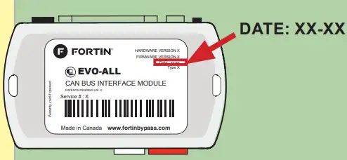
Data Bypass and Interface Module
![]() ONLY COMPATIBLE WITH AUTOMATIC TRANSMISSION VEHICLES.
ONLY COMPATIBLE WITH AUTOMATIC TRANSMISSION VEHICLES.

VEHICLE YEARS
BUICK
Encore Push-To-S t ar t 2017-2020
CHEVROLET
Trax Push-To-S t ar t 2017-2024
Vehicle functions supported in this diagram (functional if equipped)
| • | Immobilizer by pass |
| • | Lock |
| • | Unlock |
| • | Arm |
| • | Disarm |
| • | Trunk (open ) |
| • | RAPDisable |
| • | Tachometer |
| • | Heated Seats |
| • | Door Status |
| • | Trunk Status |
| • | Hand – Brake Stat us |
| • | Foot- Brake Status |
| • | OEM Remote Monitoring |

FIRMWARE VERSION VERSION LOGICIELLE 70.[45] GM MINIMUM
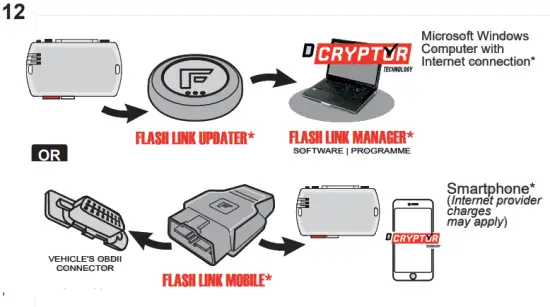
To add the firmware version and the options, use the FLASH LINK UPDATER or FLASH LINK MOBILE tool, sold separately.
Program bypass option:
IF THE VEHICLE IS NOT EQUIPPED WITH FUNCTIONAL HOOD PIN:
| UNIT OPTION | DESCRIPTION |
| C1 | OEM Remote status (Lock/Unlock) monitoring |
| A11 OFF NON | Hood trigger (Output Status). |
| D6 | Push-to-Start |
![]() ATTENTION!
ATTENTION!
E5
| OFF NON |
SPECIAL FUNCTIONS: BY DEFAULT DEACTIVATED |
| ON OUI |
MANUFACTURED MODULES BETWEEN: 04/2018 TO04/2019 |
![]() Parts required (Not included)
Parts required (Not included)
1X 5 Amp Fuse
1X 1k Ohm Resistor
MANDATORY INSTALL
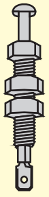
* HOOD PIN
 HOOD STATUS : THE HOOD PIN SWITCH MUST BE INSTALLED IF THE VEHICLE CAN BE REMOTE STARTED WITH THE HOOD OPEN, SET FUNCTION A11 TO OFF.
A11 OFF
NON
Notice: the installation of safety elements are mandatory. The hood pin is an essential security element and must be installed.
THIS MODULE MUST BE INSTALLED BY A QUALIFIED TECHNICIAN. A WRONG CONNECTION CAN CAUSE PERMANENT DAMAGE TO THE VEHICLE.
This guide may change without notice. See www.fortin.ca for latest version.
PARTS REQUIRED
(NOT INCLUDED)
![]() FLASH LINK UPDATER,
FLASH LINK UPDATER,
![]() FLASH LINK MANAGER
FLASH LINK MANAGER
SOFTWARE | PROGRAMME
![]() Microsoft Windows Computer with Internet connection Ordinateur Microsoft Windows avec connection Internet
Microsoft Windows Computer with Internet connection Ordinateur Microsoft Windows avec connection Internet
![]() 1x FLASH LINK MOBILE
1x FLASH LINK MOBILE
![]() 1x FLASH LINK MOBILE APP
1x FLASH LINK MOBILE APP
![]() 1x Smartphone AndroId or iOS with Internet connection (provider charges may apply
1x Smartphone AndroId or iOS with Internet connection (provider charges may apply
MANDATORY
HOOD PIN
CONTACT
REMOTE START SAFETY OVERRIDE SWITCH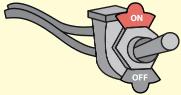 VALET SWITCH COMMUTATEUR VALET
Part #: RSPB available, Sold separately.
Notice: the installation of safety elements are mandatory.
The hood pin and the valet switch are essential security elements and must be installed.
STAND ALONE CONFIGURATION
Program bypass option
OEM Remote Stand Alone Remote Starter:
| UNIT OPTION | DESCRIPTION |
| D1.10 |
By default, LOCK, LOCK, LOCK |
| D1.1 |
LOCK, UNLOCK, LOCK |
Program bypass option with oem remote:
| UNIT OPTION | DESCRIPTION |
| C1 | OEM Remote Monitoring |
 Program bypass option with RF KIT antenna:
| UNIT OPTION | DESCRIPTION |
| H1 to H6 | Supported RF Kits and select RF Kit |
REMOTE STARTER FUNCTIONALITY

All doors must be closed.

Press the OEM remote’s Lock button 3x to remote-start (or remote-stop) the vehicle.

The vehicle will START.
REMOTE STARTER DIAGNOSTICS
MODULE RED LED
| x2 flash : | Brake ON |
| x3 flash : | No tach |
| x4 flash : | Ignition before start |
| x5 flash : | Hood Open |
REMOTE STARTER WARNING CARD
![]() CUT THIS WARNING CARD AND STICK IT ON A VISIBLE PLACE: or use the package RSPB, Sold separately.
CUT THIS WARNING CARD AND STICK IT ON A VISIBLE PLACE: or use the package RSPB, Sold separately.
![]() WARNING
WARNING
REMOTE STARTER
THE VEHICLE CAN BE STARTED BY EITHER: PRESSING THE LOCK BUTTON ON THE OEM REMOTE 3 TIMES CONSECUTIVELY OR BY A SMARTPHONE. TURN ON THE SAFETY SWITCH LOCATED UNDER THE DASHBOARD BEFORE WORKING ON THE VEHICLE.
DESCRIPTION

AUTOMATIC TRANSMISSION WIRING CONNECTION

KEY BYPASS PROGRAMMING PROCEDURE 1/3

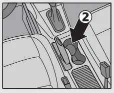
- Remove the battery from the OEM remote.
- Place the OEM remote in the front cup holder in the center console.
Refer to vehicule user guide for keyport location.
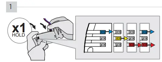
Press hold and the programming button: Connect the 4-PIN Data-link harness (Black connector).
![]() The Blue, Red, Yellow and Blue & Red LEDs will alternatively illuminate.
The Blue, Red, Yellow and Blue & Red LEDs will alternatively illuminate.
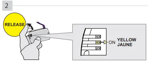
If the LED is not solid YELLOW the 4-Pin connector Release the programming button when the LED is YELLOWdisconnect.
(Data-Link) and go back to step 1.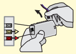
Insert the required remaining connectors.
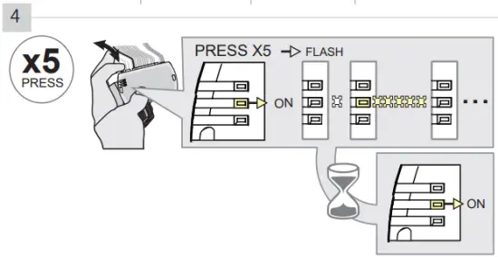
Press releaseand the programming button five (5x) times.
![]() The YELLOWLED will flash 5 times each second.
The YELLOWLED will flash 5 times each second.
![]() WAIT for the YELLOW LED to turn ON solide.
WAIT for the YELLOW LED to turn ON solide.
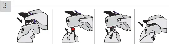
 Open the driver door.

Press the foot-brake pedal.
Release the foot-brake pedal.
Press the Push-to-Start button until the engine start.
![]() The RED LED will turn ON.
The RED LED will turn ON.
![]() The YELLOW LED will turn OFF.
The YELLOW LED will turn OFF.
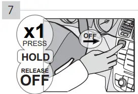
Press the Push-to-Start button until the engine turn OFF.
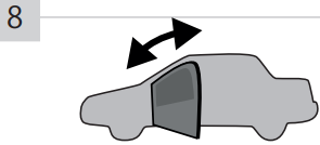
Close and open the driver door.

Press the foot-brake pedal.
Press the Push-to-Start button until the engine start.
Release the foot-brake pedal.
The BLUE LED will turn ON.
![]() The BLUE LED will turn OFF. The RED LED will turn OFF.
The BLUE LED will turn OFF. The RED LED will turn OFF.
![]() The YELLOW LED will flash rapidly
The YELLOW LED will flash rapidly
![]() The BLUE LED will turn ON.
The BLUE LED will turn ON.
![]() The BLUE LED will flash rapidly
The BLUE LED will flash rapidly

Press the Push-to-Start button until the engine turn OFF.
![]() The BLUE LED will flash slowly
The BLUE LED will flash slowly
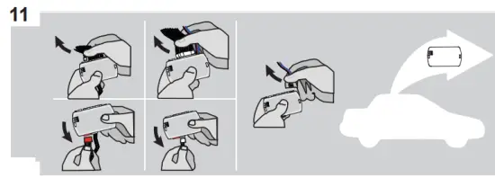
Disconnect all the connectors and after the Data-Link (4-pins) connector.
Use the tool:
FLASH LINK UPDATER or
FLASH LINK MOBILE
to visit the DCryptor menu.
*Parts required (not included)

AFTER DCRYPTOR PROGRAMMING COMPLETED
Go back to the vehicle and reconnect the 4-Pin (Data-Link) connector and after, all the remaining connector.
![]() The module is now programmed.
The module is now programmed.
![]() REMOTE STARTER / ALARM VERIFICATION
REMOTE STARTER / ALARM VERIFICATION
Test the remote starter. Remote start the vehicle.
REMOTE STARTER FUNCTIONALITY

All doors must be closed.
Remote start the vehicle.
Unlock the doors with either:
- The OEM remote
- The remote-starter remote.

Enter the vehicle with the Intelligent key.
The vehicle can now be put in to gear and driven.
![]() If the vehicle is not unlocked with one of these conditions, the remote-starter will shut down as soon as any door is opened.
If the vehicle is not unlocked with one of these conditions, the remote-starter will shut down as soon as any door is opened.
WARNING
The information on this sheet is provided on an (as is) basis with no representation or warranty of accuracy whatsoever.
It is the sole responsibility of the installer to check and verify any circuit before connecting to it. Only a computer safe logic probe or digital multimeter should be used. FORTIN ELECTRONIC SYSTEMS assumes absolutely no liability or
responsibility whatsoever pertaining to the accuracy or currency of the information supplied. The installation in every case is the sole responsibility of the installer performing the work and FORTIN ELECTRONIC SYSTEMS assumes no liability or responsibility whatsoever resulting from any type of installation, whether performed properly, improperly or any other way. Neither the manufacturer or distributor of this module is responsible of damages of any kind indirectly or directly caused by this module, except for the replacement of this module in case of manufacturing defects. This module must be installed by qualifi ed technician. The information supplied is a guide only. This instruction guide may change without notice. Visit www.fortinbypass.com to get the latest version.
![]() TECH SUPPORT
TECH SUPPORT
Tél: 514-255-HELP (4357)
1-877-336-7797
![]() ADDENDUM GUIDE
ADDENDUM GUIDE
www.fortinbypass.com
WEB UPDATE | MISE À JOUR INTERNET![]()
Documents / Resources
 |
FORTIN EVO-ALL Data Bypass and Interface Module [pdf] Installation Guide EVO-ALL Data Bypass and Interface Module, EVO-ALL, Data Bypass and Interface Module, and Interface Module, Interface Module |
 |
FORTIN EVO-ALL Data Bypass and Interface Module [pdf] Installation Guide EVO-ALL Data Bypass and Interface Module, EVO-ALL, Data Bypass and Interface Module, Bypass and Interface Module, Interface Module |
 |
FORTIN EVO-ALL Data Bypass and Interface Module [pdf] Installation Guide EVO-ALL, EVO-ALL_IG_REG_BI_TOY-RAV4-PRIME-PTS_2021_A_100041, EVO-ALL Data Bypass and Interface Module, EVO-ALL, Data Bypass and Interface Module, and Interface Module, Interface Module, Module |
 |
FORTIN EVO-ALL Data Bypass and Interface Module [pdf] Installation Guide EVO-ALL, 111651, 88. 33, EVO-ALL Data Bypass and Interface Module, EVO-ALL, Data Bypass and Interface Module, Bypass and Interface Module, Interface Module |