ENGO CONTROLS ECB8-230 Wired Control Box for Underfloor Heating System

- Product: ECB8-230 Wired Control Box for Underfloor Heating System
- Power Supply: 230V AC 50Hz
- Total Load: 6 (3) A
- Max Pump Load: 3A
- Max Boiler Load: 6A
- Max Actuator Load: 2A
- Max Thermostat Load: 1A
- Dimensions: 327 x 110 x 37 mm
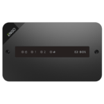
The ECB8-230 control box is the main element of the underfloor heating control system. It controls heat sources and pump, allowing for control of 8 different zones. Equipped with 230V AC voltage outputs for actuators and pluggable terminal blocks for wiring connections.
Product Usage Instructions
Safety Information
Ensure the control box is disconnected from the power supply before replacing the fuse. The main fuse is located under the housing cover next to power supply terminals.
The power supply for the wiring centre is 230V AC 50Hz. The red LED indicates the connection to the power supply.
The PUMP OUTPUT powers the circulation pump in the heating system with a maximum load of 3A. The pump starts 3 minutes after receiving a heating signal and stops when no thermostats report heat demand.
- Q: What type of actuators does the control box work with?
A: The control box is designed to work with NC (normally-closed) type actuators. - Q: How do I replace the fuse in the control box?
A: To replace the fuse, ensure the control box is disconnected from the power supply. Use ceramic tube slow blow 250V ROHS fuses (5×20 mm) with a nominal max current of 6.3A. Remove the fuse holder with a flat screwdriver and pull out the fuse.
Control Box description
- Cartridge fuse 5 x 20 mm T6,3A
- Power supply (AC 230V)
- Pump control output (AC 230V)
- Boiler control output (volt free)
- Thermostats input connections
- Actuators output connections (AC 230V)
- LED diodes indicators for the operation status of the pump, boiler and control box power supply connection
- LEDs 1 to 8 informing about the operation of zones 1-8

Introduction
ECB08M230 control box is the main element of the underfloor heating control system. It has a built-in modules that controls the heat sources (by volt-free relay) and pump (230V AC). The control box allows to control 8 different zones. It is equipped with 230V AC voltage outputs actuators. Pluggable terminal blocks provide quick and convenient wiring connections. The control box is designed to work with NC (normally-closed) type actuators.
Product compliance
This product complies with the essential requirements and other relevant provisions of the following EU Directives: EMC 2014/30/EU, Low Voltage Directive LVD 2014/35/EU, RoHS directive 2011/65/EU.
Safety information
Use in accordance with national and EU regulations. Device is intended for indoor use only in dry conditions. Product for indoor use only. Installation must be carried out by a qualified person in accordance to national and EU regulations. Before attempting to setup and install, make sure that ECB08M230 is not connected to any power source. Installation must be carried out by a qualified person. Incorrect installation may cause damage to the wiring centre. The ECB08M230 should not be installed in areas where it may be exposed to water or damp conditions.
PLEASE NOTE:
For the entire installation, there may be additional protection requirements, which the installer is responsible for maintaining.
Technical Information
| Power Supply | 230 V AC 50 Hz |
| Total Load Max | 6 (3) A |
| Pump Load Max | 3A |
| Boiler Load Max | 6A |
| Actuator Load Max | 2A |
| Thermostat Load Max | 1A |
| Outputs | Pump control (230V AC) Boiler control (NO/COM/NC) Terminals for actuators (230V AC) |
| Dimensions [mm] | 327 x 110 x 37 |
Fuse
Please note: Replacement of the fuse to be carried out only when the control box is disconnected from power supply (230 V ~ ).
Main fuse is located under the housing cover next to power supply terminals and secures the control box and the devices connected to it. Use ceramic tube slow blow 250 V ROHS fuses (5×20 mm) with nominal max current 6,3A. To replace fuse remove the fuse holder with a flat screwdriver and pull out the fuse.
Power supply

Power supply for wiring centre is 230 V ~ 50Hz.
Installation features:
- Three-wire,
- Made in accordance with applicable regulations.
![]() The red LED indicates that the wiring centre is connected to the power supply.
The red LED indicates that the wiring centre is connected to the power supply.
Pump control output (AC 230V)
The PUMP OUTPUT is used to power the circulation pump in the heating system. It is a 230V AC voltage output with a maximum load capacity of 3A. The pump is connected directly to the contacts. The out but is turned on (the pump starts) always after 3 minutes from the moment of receiving a heating signal from any thermostat connected to the wiring centre. The output is turned off (the pump stops) as soon as the last thermostat stops reporting heat demand.


When the Pump/Valve control output is activated, the pump status LED shows a constant green light.
PLEASE NOTE: Before starting the installation, disconnect the 230V power supply!
Boiler control output (volt free)
The boiler control output is supported by a relay with voltage-free contacts (NO / COM / NC output). The boiler must be connected to the COM-NO or COM-NC contacts. It is a typical two-state relay. In most cases, the NC terminal is not used. If the thermostats connected to the wiring centre send a signal for heating, the BOILER output contacts activate the relay with a 3-minute delay, allowing the boiler to be turned on. The boiler is turned off immediately, when none of the zones sends a signal for heating.

Thermostats input connections
- a – 230V thermostat connection (with COM/NO voltage-free contacts), e.g. El OW230WlFl / E10B230WlFl
- b – Connecting a battery ON / OFF thermostat (with voltage-free COM/ NO contacts), e.g. E901
- c – 230V thermostat connection (with SL – 230V voltage output)

| L | 230 V live terminal |
| N | Neutral |
| SL1 … SL8 | 230 V control signal |
| SL | Output thermostat signal 230 V AC |
Actuators output connections (AC 230V)
Actuators wires should be plugged into the pluggable terminal blocks of the respective zones. Maximum current load for each zone is designed to handle up to 6 actuators with a power of 2W each. With more actuators in one zone, an additional relay should be used to make sure that actuators output will be not overloaded.

Example based on E30NC230 actuators.
INSTALLATION

- Remove the top cover of the control box.
- Remove the appropriate piece of insulation from the wires.
 Connect the wires in accordance with the connection description.
Refer to the sticker under the top cover.- After making sure all wires are properly connected, mount the top cover and turn the wiring centre to the 230 V power supply – the red “Power” diode will light up.
Producer:
Engo Controls sp z 0.0. sp. k.
4 Rolna St.
43-262 Kobielice
Poland
www.engocontrols.com
Documents / Resources
 |
ENGO CONTROLS ECB8-230 Wired Control Box for Underfloor Heating System [pdf] User Guide ECB8-230 Wired Control Box for Underfloor Heating System, ECB8-230, Wired Control Box for Underfloor Heating System, Control Box for Underfloor Heating System, Underfloor Heating System, Heating System |
 |
ENGO CONTROLS ECB8-230 Wired Control Box for Underfloor Heating System [pdf] Instruction Manual ECB8-230, ECB8-230 Wired Control Box for Underfloor Heating System, Wired Control Box for Underfloor Heating System, Control Box for Underfloor Heating System, Underfloor Heating System, Heating System |