![]() CONTROL BOX
CONTROL BOX
ECB2-230 | 2 Heating circuits module
 Quick Guide
Ver. 1.4
Release date: II 2024
Soft: v1.3
Introduction
The heating circuit module makes it possible to operate two independent heat zones to which temperature controllers and circulation pumps are connected. It is used in typical single-family housing, where there are divisions into 2 heating circuits (e.g. 1 first floor circuit and 2 floor circuit).
Then the signal coming from any of the heating circuits activates the outputs to the main circulation pump and the heat source in the controller. The integrator can also be used for small (e.g. two-zone) floor heating systems.
Product compliance
This product complies with the essential requirements and other relevant provisions of the following EU Directives: EMC 2014/30/EU, Low Voltage Directive LVD 2014/35/EU, RoHS directive 2011/65/EU.
 Safety information
Use in accordance with national and EU regulations. Device is intended for indoor use only in dry conditions. Product for indoor use only. Installation must be carried out by a qualified person in accordance to national and EU regulations.
Before attempting to setup and install, make sure that ECB02M230 is not connected to any power source. Installation must be carried out by a qualified person. Incorrect installation may cause damage to the wiring centre. The ECB02M230 should not be installed in areas where it may be exposed to water or damp conditions.
PLEASE NOTE:
For the entire installation, there may be additional protection requirements, which the installer is responsible for maintaining.
Technical Information
| Power Supply | 230 V AC 50 Hz |
| Total Load Max | 6(1)A |
| Outputs: | Pump230V AC max. 3(1)A Boiler (NO/COM/NC) max. 6(1)A |
| Dimensions [mm] | 150 x 90 x 35 |
Control Box description
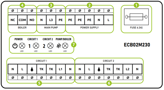
- Cartridge fuse 5 x 20 mm T6,3A
- Power supply (AC 230V)
- Main pump control output (AC 230V)
- Boiler control output (volt free)
- Circuit 1 – connection contacts
- Circuit 2 – connection contacts
- LED diodes indicators:
• power supply connection
• circuit 1 is activated
• circuit 2 is activated
• boiler and main pump is activated
Fuse
![]() Please note: Replacement of the fuse to be carried out only when the control box is disconnected from power supply (230 V ~)..
Please note: Replacement of the fuse to be carried out only when the control box is disconnected from power supply (230 V ~)..
Main fuse is located under the housing cover next to power supply terminals and secures the control box and the devices connected to it. Use ceramic tube slow blow 250 V ROHS fuses (5×20 mm) with nominal max current 6,3A. To replace fuse remove the fuse holder with a flat screwdriver and pull out the fuse.
Power supply

Power supply for wiring centre is 230 V ~ 50Hz.
Installation features:
- three-wire,
- made in accordance with applicable regulations.
![]() The red LED indicates that the wiring centre is connected to the power supply.
The red LED indicates that the wiring centre is connected to the power supply.
Boiler and main pump outputs
The MAIN PUMP and BOILER outputs are used to control the main circulating pump and the heat source in the heating system. The outputs are turned on when a heating signal is received from any room controller connected to the integrator. The outputs are turned off when none of the controllers sends a signal for heating.

![]() The green LED indicates that the BOILER & MAIN PUMP output is activated.
The green LED indicates that the BOILER & MAIN PUMP output is activated.
Circuit connection contacts
a) – Connecting a battery thermostat (with voltage-free COM / NO contacts)

b) – 230V thermostat connection (with SL – 230V voltage output)
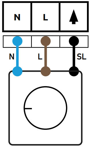
c) – 230V thermostat connection (with COM / NO voltage-free contacts)

d) – Wireless thermostats receiver connection (with COM / NO voltage-free contacts)

Circuit connection contacts
If the integrator was used for underfloor heating, additional thermal protection can be used (e.g., a bimetallic touch thermostat).
If the temperature is exceeded, the thermal protection will turn off the circulation pump in the circuit in question

If thermal protection is not used, a short circuit should be used in its place

Circulation pump/actuator output

![]() The green LED1, LED2 indicates that the circulation pump/actuator output is activated
The green LED1, LED2 indicates that the circulation pump/actuator output is activated
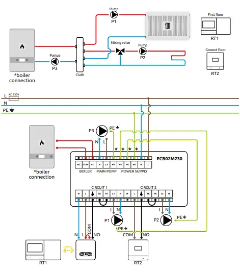
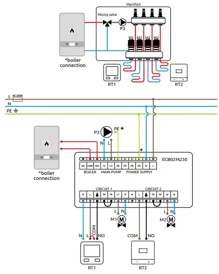
Wiring diagrams
Below are sample wiring diagrams of the integrator. Hydraulic diagrams are illustrative and are not a substitute for the design of the CO system.
a) – Connection of 2 heating circuits
 b) – Connection of 2 underfloor heating zones
c) – Connection of 2 heating sources

Legend
| Boiler *- ON/OFF contacts (according to the boiler’s manual) | |
| Mixing or switch valve | |
| Pump | |
| Valve actuator | |
| Hydraulic coupling | |
| Radiator heating | |
| Underfloor heating |
![]() – Fuse
– Fuse
L, N – 230V AC power suply
COM, NO, NC – Voltage-free output
RT1 – Circuit 1 thermostat
RT2 – Circuit 2 thermostat
P1 – Circuit 1 circulation pump
P2 – Circuit 2 circulation pump
P3 – Main pump
M1 – Circuit 1 actuator
M2 – Circuit 2 actuator
![]() Producer:
Producer:
Engo Controls Sp. z o.o. Sp. k.
43-262 Kobielice
4 Rolna St.
Poland
www.engocontrols.com
Documents / Resources
 |
ENGO CONTROLS ECB2-230 2 Heating Circuit Module [pdf] User Guide ECB02M230, ECB2-230 2 Heating Circuit Module, ECB2-230, 2 Heating Circuit Module, Heating Circuit Module, Circuit Module, Module |