DAUDIN MELSEC-Q Modbus TCP Connection
Product Information
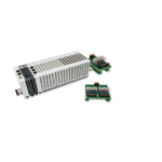
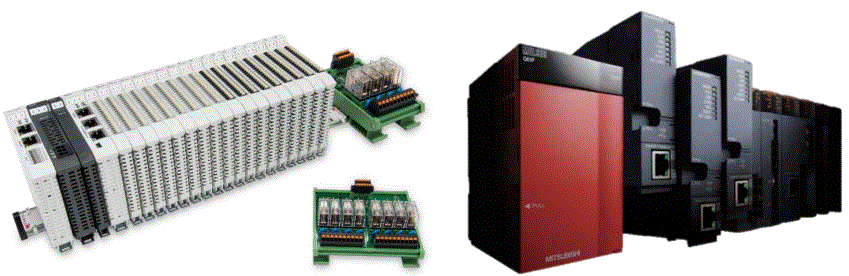
The 2302EN V2.0.0 and MELSEC-Q Modbus TCP Connection Operating Manual provides instructions on how to connect and configure a remote I/O module system using various components including a Modbus TCP-to-Modbus RTU/ASCII gateway, a Master Modbus RTU main controller, Digital Input and Output modules, and Power Supply modules. The gateway is used externally to connect with MELSEC-Q series’ communication port (Modbus TCP) and the main controller is in charge of the management and dynamic configuration of I/O parameters and so on. The power module is standard for remote I/Os and users can choose the model or brand of power module they prefer.
Product Usage Instructions
Remote I/O Module System Configuration List
The Remote I/O Module System Configuration List provides a list of the various modules that can be used to configure the system including the Gateway, Main Controller, Digital Input and Output modules, and Power Supply modules. Each module has a Part No., Specification, and Description.
Gateway Parameter Settings
The Gateway Parameter Settings section details how to connect a gateway to MELSEC-Q series. For detailed information regarding these settings, please refer to the Series Product Manual.
i-Designer Program Setup
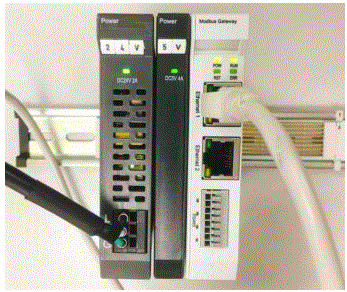
- Make sure that the module is powered and connected to the gateway module using an Ethernet cable.
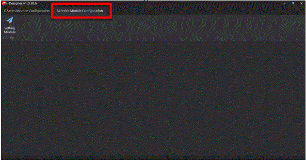
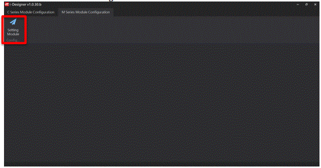
- Launch the i-Designer software.
- Select M Series Module Configuration.
- Click on the Setting Module icon.
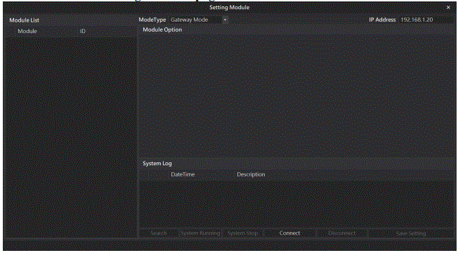
- Enter the Setting Module page for M-series.
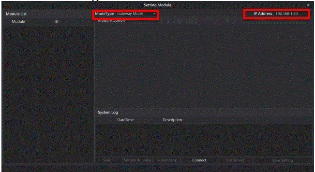
- Select the mode type based on the connected module.
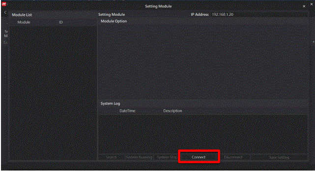
- Click on Connect.
- Configure the Gateway Module IP Settings. Note: The IP address must be in the same domain as the MELSEC-Q controller.
- Configure the Gateway Module Operational Modes. Note: Set Group 1 as Slave and set the gateway to use the first set of RS485 port to connect to the main controller (GFMS-RM01N).
MELSEC-Q series Connection Setup
The MELSEC-Q series Connection Setup chapter explains how to use the GX Works2 program to use the QJ71MT91 module to connect MELSEC-Q series to a gateway module and add a remote I/O module. For detailed information, please refer to the MELSEC-Q Series Manual.
MELSEC-Q series Hardware Connections
- The QJ71MT91 module’s Ethernet port is at its bottom center and can be connected to the gateway.
MELSEC-Q series IP Address and Connection Setup
- Launch GX Works 2 and right-click on the Intelligent Function Module menu under Project on the left side.
- Click on New Module to create a QJ71MB91 module.
Remote I/O Module System Configuration List
| Part No. | Specification | Description |
| GFGW-RM01N |
Modbus TCP-to-Modbus RTU/ASCII, 4 Ports |
Gateway |
| GFMS-RM01S | Master Modbus RTU, 1 Port | Main Controller |
| GFDI-RM01N | Digital Input 16 Channel | Digital Input |
| GFDO-RM01N | Digital Output 16 Channel / 0.5A | Digital Output |
| GFPS-0202 | Power 24V / 48W | Power Supply |
| GFPS-0303 | Power 5V / 20W | Power Supply |
Product Description
I. The gateway is used externally to connect with MELSEC-Q series’ communication port (Modbus TCP)
II. The main controller is in charge of the management and dynamic configuration of I/O parameters and so on.
III. The power module is standard for remote I/Os and users can choose the model or brand of power module they prefer.
Gateway Parameter Settings
This section details how to connect a gateway to MELSEC-Q series. For detailed information  , please refer to the
![]() Series Product Manual
Series Product Manual
Designer Program Setup
- Make sure that the module is powered and connected to the gateway module using an Ethernet cable
- Click to launch the software

- Select “M Series Module Configuration”
- Click on the “Setting Module” icon
- Enter the “Setting Module” page for M-series
- Select the mode type based on the connected module
- Click on “Connect”Note: The IP address must be in the same domain as the MELSEC-Q controller
- Gateway Module IP Settings
 Note: The IP address must be in the same domain as the MELSEC-Q controller
 - Gateway Module Operational Modes
Note: Set Group 1 as Slave and set the gateway to use the first set of RS485 port to connect to the main controller (GFMS-RM01N)
MELSEC-Q series Connection Setup
This chapter explains how to use the GX Works2 program to use the QJ71MT91 module to connect MELSEC-Q series to a gateway module and add a remote I/O module. For detailed information, please refer to the “MELSEC-Q Series Manual
MELSEC-Q series Hardware Connections
- The QJ71MT91 module’s Ethernet port is at its bottom center and can be connected to the gateway
MELSEC-Q series IP Address and Connection Setup
- Launch GX Works 2 and right click on the “Intelligent Function Module” menu under “Project” on the left side. Then click on “New Module” to create a “QJ71MB91” module
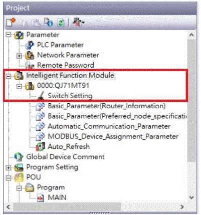
- Launch GX Works 2 and select the “Intelligent Function Module” menu under “Project” on the left side. Then click on “Switch Setting” in the “QJ71MT91” menu
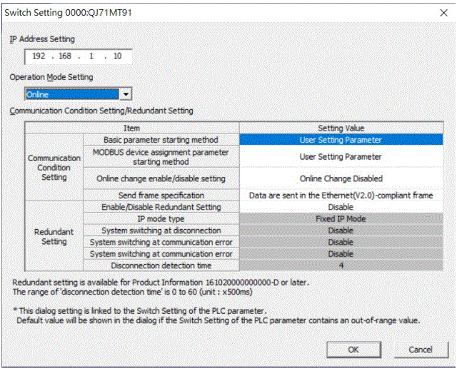
- Set “IP Address” to the same domain as the gateway domain at 192.168.1.XXX.
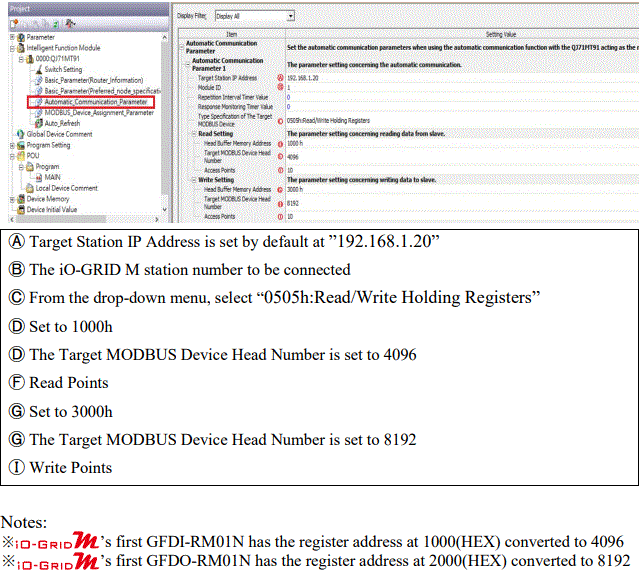
- Click on “Automatic_Communication_Parameter” to set up reading and writing methods
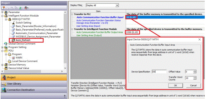
- Click on “Auto_Refresh” to set up the internal register for reading and writing
Simple Program Demonstration using MELSEC-Q series and
The ’s read register address is 4096, which is D0 for the corresponding internal register of the controller.
And the ’s write register address is 8192, which is D300 for the corresponding internal register of the controller.
Therefore, when you want to control the program, you can just use the internal register to control the writing and reading.

Documents / Resources
 |
DAUDIN MELSEC-Q Modbus TCP Connection [pdf] User Manual MELSEC-Q Modbus TCP Connection, MELSEC-Q, Modbus TCP Connection, Modbus |