![]()
Installation guide
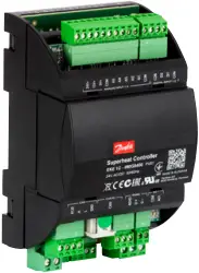
Back up power module
Type EKE 2U
![]()
Introduction
EKE 2U module is an optional energy storage device. The module can provide enough energy during power failure to the stepper controller to ensure closure of the electronic valves. It can be used with one or two controllers depending on the application.
State of Health (SOH) function of EKE 2U gives feedback to controllers to detect the status of the backup module and lets the controller know if the backup is Ready to use, Charging or Failed.
Power Failure signal (PF): This signal should be connected to controller only if the controller cannot detect power failure by itself. Not required for EKE controllers.
Load Switch, EKE 2U can deliver power backup for 2 valves. While using more than 1 valve the load switch can be changed to deliver more energy.
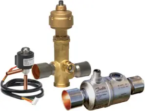
Compatible Controllers: Danfoss EKE series and MCX controllers. For other controllers, please contact Danfoss.
 More info
Wiring Diagram

- LOAD SWITCH
- SoH communication (optional)
Info for UK customers only: Danfoss Ltd., 22 Wycombe End, HP9 1NB, GB
![]() 080R9346
080R9346
![]()
Dimensions in mm
EKE 2U
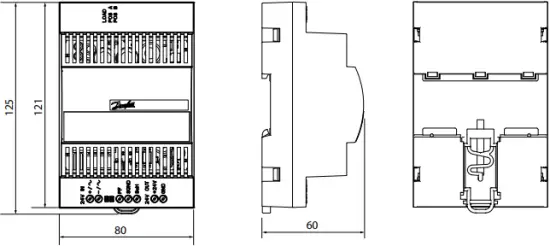
Weight: 233 gram
Technical specifications
| Nominal input voltage | 24 V DC / 24 V AC |
| Input voltage range | 20 – 40 V DC, 19 – 29 V AC |
| Frequency | DC / AC 50 … 60 Hz + /-10% |
| Overvoltage capability | < 42 V DC < 30 V AC |
| Nominal input power | DC: 15 VA, AC: 25 VA |
| Protection class | II |
| Inrush current | < 15 A |
| Standby current @ 24 V DC | ~ 0.1 A |
| Nominal output voltage (UNOM) | 24.0 V DC ± 2% |
| Nominal output current (INOM) | 2 A |
| Maximum output current on standby | 30 mA |
| Current limiting | 2.5 A ± 10% |
| Parallel connection for time increase | yes |
| Series connection | no |
| Capacitor charging current @ 24 V DC | < 1 A |
| Charging time | ~ 2.5 min from fully discharged state |
| Max Voltage / current at X2 (open collector) | 24V / 8.5 mA |
| Ambient temperature during operation | TAMB = -25 °C – + 60 °C |
| Storage temperature | – 30 °C – + 70 °C |
| Humidity | < 90 % rH, no condensation. |
| Environmental pollution | Type 2 |
| Protection degree | IP 20 |
| Altitude | Up to 2000 m |
| Immunity to voltage Surges EN 61000-4-5 | Level 3 in/out Level 2 signals |
| Assembly | On DIN rail |
| Overvoltage protection | Category II |
| Lifespan | >90000 hours (10 years) @ 35 °C and >3 years @ 50 °C |
| MTBF | > 500.000 h @ 25 °C according to IEC 61709 / SN 29500 |
Recommended Load Switch Position
| Valve Type | Number of valves | |
| 1 Valve | 2 Valves | |
| ETS 5M / ETS 6 | POS B | POS A |
| ETS Colibri | POS B | POS B |
| ETS 12.5 to 100, ETS 250, ETS 400 | POS B | POS B |
| KVS 15/42 | POS B | POS B |
| CCMT / CCM | POS B | POS A |
![]() Important Notes :
Important Notes :
- Load switch POS A and POS B defines the max energy supplied by the EKE 2U as power backup.
- POS A delivers more energy than POS B. Using at POS B further increases lifetime of EKE 2U.
- Load switch has default position POS A and POS A will work throughout all combinations.
| State of Health (SOH) | Function | LEDs |
| Ready | Backup is ready and controller can start operating valves. | Green on Red off |
| Charge | Backup module is charging. Controller must not operate valves. | Green flashing. 1 Hz Red off |
| Replace | Backup module needs to be replaced. But valves can be operated. | Green: Ready or Charge Red on. |
| Failure | Backup module does not work. Controller can still operate valves. But at a power loss no guarantee that the valves can close. | Green off Red flashing. 1Hz |
Cable length
EKE 2U supports the following max. cable length.
| Cable length [m] |
Wire size min. / max. [mm²] |
|
| Power supply Input | max. 5 | 0.2 / 1.5 |
| Backup output | max. 5 | 0.2 / 1.5 |
| Digital outputs | max. 5 | 0.2 / 1.5 |
Cable and wiring
- Keep power and battery backup cable separate from SOH cable
General features and warnings
Plastic housing features
-DIN rail mounting
-Self-extinguishing V0
Other features
-Operating conditions CE: -25T60, 90% RH non-condensing
-Storage conditions: -30T70, 90% RH non-condensing
-Max duty-cycle Charge/Discharge at nominal load 15min ON / 10s OFF
-To be integrated in Class I and/or II appliances
-Index of protection: IP 20
-Period of electric stress across insulating parts: long
-Suitable for using in a normal pollution environment
-Immunity against voltage surges: category II
Safety and approvals
This product is designed to comply with the following standards:
-EN61000-6-1, EN61000-6-3 (immunity for residential, commercial and light-industrial environments)
-EN61000-6-2, EN61000-6-4 (immunity and emission standard for industrial environments)
-UL 61010
-IEC 61010-2-201:2013
General warnings
-Every use that is not described in this manual is considered incorrect and is not authorized by the manufacturer
-Verify that the installation and operating conditions of the device respect those specified in the manual, especially concerning the supply voltage and environmental conditions
-This device contains live electrical components. All service and maintenance operations must therefore be performed by qualified personnel
-The device must not be used as a safety device
-Liability for injury or damage caused by the incorrect use of the device lies solely with the user
-The manufacture’s guarantee expires in the event of improper use
 Installation warnings
-Intended mounting position: vertical
-Installation must comply with local standards and legislation
-Before working on the electrical connections, disconnect the device from the main power supply
-Before carrying out any maintenance operations on the device, disconnect all electrical connections
-For safety reasons the appliance must be fitted inside an electrical panel with no live parts accessible
-Do not expose the device to continuous water sprays or to a relative humidity greater than 90%
-Avoid exposure to corrosive or pollutant gases, natural elements, environments where explosives or mixes of flammable gases are present, dust, strong vibrations or shock, large and rapid fluctuations in ambient temperature that might cause condensation in combination with high humidity, strong magnetic and/or radio interference (e.g. transmitting antennae)
-When connecting loads be aware of the maximum current for each relay and connector
-Use cable ends suitable for the corresponding connectors. After tightening connector screws, tug the cables gently to check their tightness
-Use appropriate data communication cables. Refer to the EKE data sheet for the kind of cable to be used and setup recommendations
-Minimize the length of probe and digital input cables as much as possible and avoid spiral routes around power devices. Separate from inductive loads and power cables to avoid possible electromagnetic noises
-Avoid touching or nearly touching the electronic components fitted on the board to avoid electrostatic discharges
-Use copper cables for operating temperatures >75 °C (ambient temperature ≤ 60 °C)
Product warnings
- Use a class II category transformer for 24 V AC power supply
- Connecting any output signals to mains voltage will permanently damage the controller

DIN rail mounting / demounting
The unit can be mounted onto a 35 mm DIN rail simply by snapping it into place and securing it with a stopper to prevent sliding. It is demounted by gently pulling the stirrup located in the base of the housing.


- Power sharing is allowed between EKE 2U power backup module and EKE SH controllers provided power supply is DC.
- Max 2 EKE controller should be connected to 1 EKE 2U
- SOH signal should not be shared. It should be connected to only one EKE controller and the readouts should be taken from this controller.

SHARING EKE 2U WITH 2 CONTROLLERS
- DC Power supply
- Danfoss
80G295.10 - SoH Signal
Quick guide for parameter selection in EKE controllers
Start : Main switch= Off
Make sure that main switch is OFF before changing the settings. The setting will depend on the system requirement.
Parameter: R012 Main Switch
![]()
Select DI2 configuration
Set DI2 to PWR backup status. This should be used only if EKE 2U SOH is connected to DI2 of EKE 1.
Enables EKE 1to read SOH signal.
Parameter: O022 DI2 configuration
![]()
Battery Alarm
Battery alarm function must be set ON/OFF depending on the signal needed. If set to On then EKE 1 will send alarm if EKE 2U battery is low.
Parameter: A034 Battery alarm
![]()
Actual battery voltage read out
Using parameter U101 actual battery voltage of EKE 2U can be read through EKE 1.
Parameter: U101 Actual battery voltage
![]()
Power backup status readout
Using parameter U115. Power backup status of EKE 2U can be read from EKE 1. Only applicable if SOH is connected to DI2.
Parameter: U115 PWR Backup status
![]()
Dl1=ON
Set main switch back to ON status to start the controller.
Parameter: R012 Main switch
| Power Supply | EKE series controllers | Stepper motor valves |
 |
 |
 |
| AK-PS Input: 100 – 240 V AC, 45 – 65 Hz Output: 24 V DC: available with 18 VA, 36 VA and 60 VAACCTRD Input: 230 V AC, 50 – 60 Hz Output: 24 V AC, available with 12 VA, 22 VA and 35 VA |
EKE series preprogrammed superheat controllers/ drivers for controlling electric expansion valves. | EKE is compatible with Danfoss stepper motor valves i.e Danfoss ETS 6, ETS, KVS,ETS Colibri®, KVS colibri®, CTR, CCMT |
© Danfoss | Climate Solutions | 2021.09 AN325741621547en-000803
Documents / Resources
 |
Danfoss 080G5555 Back up Power Module [pdf] Installation Guide Type EKE 2U, 080R9346, 080G5555, 080G5555 Back Up Power Module, Back Up Power Module, Power Module |