![]()
Temperature sensor
CombiTemp TFRN/TFRH
Operating instructions

ATEX applications
Valid for FlexTop™ 2202 / 2211 / 2212 / 2221
![]() The FlexProgrammer configuration unit must not be connected to the FlexTop within the hazardous area.
The FlexProgrammer configuration unit must not be connected to the FlexTop within the hazardous area.
Configuration procedure:
a. Disconnect mains from the 4…20 mA loop circuit
b. Disconnect the product from the security within the hazardous area
c. Bring the product to the safe area
d. Connect the FlexProgrammer and perform the configuration
e. Reinstall the product in the hazardous area
f. Connect the power supply to the circuit
For FlexTop™ 2221/2222 only
Configuration for the FlexTop™ 2221/2222 can be made within the hazardous area by means of a handheld HART configurator, providing the precautions and guidelines described in the product’s manual are observed.
The CombiTemp TFRx is ATEX approved with transmitter for Ex nA for zone 2.
The CombiTemp TFRx is ATEX approved without transmitter, i.e. with Pt100 output only, as simple apparatus as Ex ia for gas and dust.
Compliance and approvals
| EMC | EN 61000-6-2 EN 61000-6-3 |
| ATEX | ATEX II 1G Ex ia IIC T4/T5 ATEX II 3G Ex nA IIC T5 Ex ia Simple apparatus, gas and dust |
| Hygiene | Regulation 1935/2004, 2023/2006 3-A (74-07) |
Field of application
CombiTemp™ TFRx is a temperature sensor, based on RTD technology, which is designed and produced to meet the requirements in food & beverage and pharmaceutical industry where hygienic connections are used.
CombiTemp™ TFRx comprises a series of basic elements which can be combined in various ways to a CombiTemp TFRx temperature sensor.
The product offers great flexibility in respect to modification, service and maintenance.
The sensor can be made to feature a RTD output signal or with a built in FlexTop™ temperature transmitter types 2202, 2211, 2212, 2221 and 2222 with 4-20 mA output (for documentation of FlexTops, please see relevant data sheet or operating instructions).
This instrument is constructed and tested according to the current EU directives and packed in technically safe condition. In order to maintain this condition and to ensure safe operation, the user must follow the instructions and warnings given in this manual.
During the installation local standards have to be observed. Ignoring the warnings may lead to severe personal injury or substantial damage to property.
The product must be operated by trained staff. Correct and safe operation of this equipment is dependent on proper transport, storage, installation and
operation.
All electrical wiring must conform to local standards and the connection must be made according to the connecting diagrams. Before switching on power supply take care that there is no unwanted interaction with other equipment. Ensure that the supply voltage and the conditions in the environment comply with the specification of the device.
Before switching off the supply voltage check the possible effects on other equipment and the processing system.
To obtain the specified protection degree, use a compliant cable for electrical installation.
![]() WARNING
WARNING
For electrical installations and commissioning of the explosion-protected devices, the data given in the conformity certificate as also the local regulations for installation of electrical apparatus within explosion-protected areas must be considered. The intrinsically safe versions can be mounted in the explosion-hazarded area according to its specification and only connected to a certified intrinsically safe supply loop with the corresponding electrical values. After mounting of the device – do check that the housing has a ground potential.
Note:
This product contains no replaceable parts. In case of malfunction, the product must be returned to Baumer for repair.
Mechanical specifications
| Sensor tube and process connection |
Stainless steel, AISI 316L (1.4404) | |
| Housing Mounting part |
Stainless steel, AISI 304 (1.4301) Stainless steel, AISI 304 (1.4301) |
|
| Electrical connection | Plug Material Cable gland Material |
M12, 5-pin or 8-pin Stainless steel AISI 304 (1.4301) M16 or M20 Plastic or Stainless steel AISI 304 (1.4301) |
Environment
| Process pressure | ≤40 bar (60 bar) |
| Process temperature | -40 … 250 °C -40 … 400 °C with cooling neck |
| Ambient temperature | -50…160°C without transmitter/display -40…85°C with transmitter only -30…80°C with transmitter and display |
| Humidity | <98% RH, condensing |
| Protection class | IP67 / IP69K |
| Vibrations | GL, test 2 (sensor tube <200 mm) |
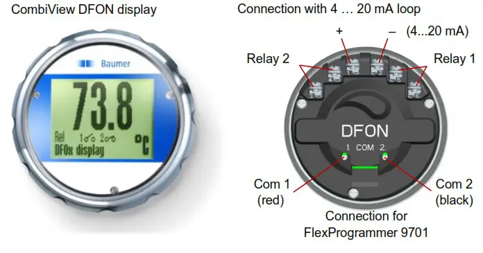
CombiView DFON display
| Type | Graphically LCD |
| Front glass | Polycarbonate |
| Display modes | 8 modes, programmable e.g. value, bar graph, analogue |
| Background colour | White, green, red – programmable |
| Measuring range | -9999…99999 |
| Digit height | Max. 22 mm |
| Accuracy | 0,1% @ ambient –10…70 °C 0,2% @ ambient –30 … -10 / 70 … 80 °C |
| Voltage drop | 4V…6,5V – depending on background light |
| Output | 2 configurable relay output, 60 Vp, 75 mA |
| Programming | Touch screen or FlexProgrammer 9701 |
| Further information can be found in separate data sheet and/or operating instructions for the Baumer graphical display, CombiView DFON. |
|
Sensor element specifications (DIN/EN/IEC 60751)
| Sensor element | Pt100 | |
| Accuracy
(sensor element) |
Class B Class 1/3 B Class 1/6 B Class A |
±(0,3 + 0,005×t)°C ±1/3 × (0,3 + 0,005×t)°C ±1/6 × (0,3 + 0,005×t)°C ±(0,15 + 0,002×t)°C |
| Single element Double element |
1 × Pt100 2 × Pt100 |
|
| Connection | 2-wire or 4-wire | |
FlexTop® 2202 temperature transmitter
| Input | Pt100 |
| Output | 4…20 mA |
| Accuracy | input < 0,25°C, span ≤ 250 °C – < 0,1% span, span > 250 °C output < 0,1% signal span (16 mA) |
| Range Minimum span |
-200…850°C 25°C |
| Voltage supply range | 8…35 V DC |
| Programmability | By FlexProgrammer 9701 |
| Further information can be found in separate data sheet and/or operating instructions for FlexTop 2202 | |
FlexTop ® 2211 and 2221 temperature transmitter
| Input | Pt100 |
| Output | 2211 4…20 mA 2221 4…20 mA / HART |
| Accuracy | input <0,1°C output <0,1% signal span (16 mA) |
| Range Minimum span |
-200…850°C 25°C |
| Voltage supply range | 2211 6,5 … 30 V DC 2221 8,0 … 35 V DC |
| Programmability | By FlexProgrammer 9701 or HART modem |
Further information can be found in separate data sheet and/or operating instructions for FlexTop 2211 or FlexTop 2221
FlexTop® 2212 and 2222 temperature transmitter
| Input | Pt100 |
| Output | 2212 4…20 mA 2222 4…20 mA / HART |
| Accuracy | input <0,06°C output <0,025% signal span (16 mA) |
| Range Minimum span |
-200…850°C 10°C |
| Voltage supply range | 7 … 40 V DC |
| Programmability | Both: Touch screen or FlexProgram 2222: By HART® modem |
Further information can be found in separate data sheet and/or operating instructions for FlexTop 2212 or FlexTop 2222
Dimensions for TFRN/TFRH housing

Dimensions for sensor tube and process connection (mm) for TFRN

Dimensions for sensor tube and process connection (mm) for TFRH

Dimensions for other options (mm)

Response time, (time constant) T50
| Sensor diameter |
Sensor tip |
Liquid 0.4 m/sec |
Air 3 m/sec |
Air 0 m/sec |
| 06 mm | Fast | <1,5 sec | <21,4 sec | <135,6 sec |
| Standard | <6,1 sec | <27,2 sec | <137,8 sec | |
| 8 mm | Fast | <1,5 sec | <33,6 sec | <181,0 sec |
| Standard | <7,6 sec | <47,7 sec | <200,9 sec |

Note:
When a thermowell is used, the time delay increases. The delay is the time duration for the sensor to reflect the correct temperature after a temperature
change in the media.
Process conditions
| Process pressure | Process tempe- rature, standard (Tamb = 20 °C) | Process temperature, with cooling neck (Tamb = 20 °C) | Process temperature, with cooling neck and spacer (Tamb = 60 °C) | |||||
| Process connection | BCID | dering Orkey | [bar] | [°C] | [°C] | [°C] | ||
| TFRN | ||||||||
| Sleeve 0 6 | T65 | 10 | -1…..40 | -50 | 250 | -50 | 400 | -50400 |
| G 1/2 A DIN 3852-E | G51 | 11 | -1…..100 | -50 | 250 | -50 | 400 | -50400 |
| G 1/2 A DIN 3852-A | G44 | 12 | -1…..100 | -50 | 250 | -50 | 400 | -50400 |
| R 1/2 ISO 7/1 | R06 | 13 | -1…..100 | -50 | 250 | -50 | 400 | -50400 |
| 1/2-14 NPT | NO2 | 30 | -1…..100 | -50 | 250 | -50 | 400 | -50400 |
| TFRH | ||||||||
| G 1/2 A hygienic | A03 | 51 | -1…..100 | -50 | 250 | -50 | 400 | N/A |
| BHC 3A DN 38 | B01 | 60 | -1…..40 | -50 | 250 | -50 | 400 | N/A |
| ISO 2852 DN38 (Tri-Clamp) | C04 | 65 | -1….40 | -50 | 250 | -50 | 400 | N/A |
| ISO 2852 DN51 (Tri-Clamp) | CO5 | 66 | -1….40 | -50 | 250 | -50 | 400 | N/A |
| Varivent0 Type N | V02 | 70 | -1….16 | -50 | 250 | -50 | 400 | N/A |

Electrical connection Pt100
To connect with Pt100 output with ceramic terminal block

To connect Pt100 output with M12 connector
 |
1 × Pt100 1 2-wire Pt100 2 3-wire Pt100 3 2-wire Pt100 4 4-wire Pt100 5 N.C |
 |
2 × Pt100 1 Pt100 (1) 2 Pt100 (1) 3 Pt100 (2) 4 Pt100 (2) 5 N.C |
Electrical connection 4 … 20 mA

To connect with M12 connector
 |
5-pin 4-20 mA 1 + supply, 4-20 mA 2 Common for relays 3 – supply, 4-20 mA 4 Relay 2 5 Relay 1 |
 |
8-pin 4-20 mA 1 N.C. 2 + supply, 4-20 mA 3 Relay 21 4 Relay 22 5 Relay 11 6 Relay 12 7 – supply, 4-20 mA 8 N.C. |
Electrical connection DFON display
Electrical connection with cable gland
Cable diameter
| M16 plastic M16 stainless steel M20 plastic M20 stainless steel |
5 … 10 mm 5 … 9 – 8 … 13 – 11 … 15 – |
![]() Check the maximum temperature for the cable used Be sure to fixate the instrument before tightening the cable gland. When using M16 stainless steel and M20 stainless steel the maximum tightening torque is 4 Nm.
Check the maximum temperature for the cable used Be sure to fixate the instrument before tightening the cable gland. When using M16 stainless steel and M20 stainless steel the maximum tightening torque is 4 Nm.
![]() When upgrading the TFRx without display with a DFON touch screen, remember to remove the O-ring from the sealing. Otherwise the sealing won’t be tight.
When upgrading the TFRx without display with a DFON touch screen, remember to remove the O-ring from the sealing. Otherwise the sealing won’t be tight.
Mounting for TFRN
The CombiTemp™ TFRN can be mounted in several different ways.
- Sensor tube without connection
Baumer offers compression glands fitting Ø6 and Ø8 mm sensor diameter. This type of mounting is normally used for mounting a sensor direct into a non-pressurized application. If pressurized, ensure that the connection is tightened correctly, so no leakage occur.
A duct channel mounting flange for 8 mm sensor is also available.

All threaded connections can be mounted directly into the application without thermowell, however often a thermowell is required to enable the user to take out the sensor for e.g. calibration without opening the system.
- Sensor with male threaded process connection G 1/2 A This is suitable in a Baumer thermowell type ZPT4. The process connections available for ZPT4 are R 1/2, G 1/2 A, G 3/4 A, M20 or with hygienic ISO 2852 clamp DN 38.
- Sensor with male threaded process connection G 3/4 A and G 1 A and sensors with G 1/2 or G 3/4 female thread can be supplied with a special thermowell. Please contact Baumer.


Mount the gland/pocket into the application and install the sensor after the gland/pocket is fixed to the application.
This will ensure that the cable is not twisted during mounting.
Baumer recommends to use a thermal compound filled into the thermowell to ensure best possible heat transfer between the pocket and the CombiTemp TFRN. Baumer offers a 6 gram bag Thermal compound, type ZPX1-001
Mounting for TFRH
Installation of 3-A and EHEDG-approved products:
![]()
Generally for welding adapters in a tank
- Use only a 3-A/EHEDG-approved counterpart.
- Level the inner surface of the tank with the welding adapter.
- If it is possible, always face the inspection hole downwards, so a leaking gasket can be observed quickly and if necessary replaced. The inspection hole should always be visible and drainable.
- Weld from the inside of the tank if possible. Welds shall be free from cracks, burr and grooves. Welding should be grinded to Ra ≤ 0.8 µm (Be sure not to grind on the edge of the adaptor hole. Otherwise the connection will not be tight)
- Tighten the connection with the torque stated below

Cleaning
Clean, disinfect or sterilize sensor as needed (CIP/SIP).
Ensure that when installed in a tank both the sensor and the connection are reached by the cleaning agents.
Generally for welding adapters in a tube
- Use only a 3-A/EHEDG approved welding adapter
- Level the inner surface of the pipe with the welding adapter.
- Welds shall be free from cracks, crevices and groves. Welding should be grinded to Ra ≤ 0.8 µm.
- The 3-A mark or arrow shall be placed upwards. Always face the inspection hole downwards, so a leaking gasket can be observed quickly. If necessary to be replaced. The inspection hole should be visible and drainable.
- Always mount the welding adapter in a self-draining position. On a tube; >5° from horizontal. This will give an optional placement of 170° for the location of measuring point (as shown in the drawing)
- Tighten the connection with the torque stated below

Tighten the connection with a torque of:
CombiTemp TFRH G 1/2 A hygienic 20 Nm
After installation and configuration
- Check the leak tightness between the welding sleeve and the instrument
- Check the tightness of glands or M12 plugs.
- Check the tightness of the instrument cover
It is important that a 3-A marked adapter are installed according to these instructions. Always try to limit cracks, crevices and holes where remaining media can accumulate and provide bacteria.
Always replace gaskets or O-rings that are damaged or defect.
Hazardous area (ATEX)
The CombiTemp™ TFRx can be supplied for hazardous area. Eithas a Simple Apparatus with RDT output or with built-in transmitter with 4 … 20 mA output.
A CombiTemp™ TFRx with built in transmitter will have two possible
ATEX approvals, Ex ia (zone 0, 1, or 2) or Ex nA (zone 2).
![]() II 1 G, EX ia IIC T4/T5, Gas
II 1 G, EX ia IIC T4/T5, Gas
![]() II 3 G, Ex nA IIC T4/T5, Gas
II 3 G, Ex nA IIC T4/T5, Gas
The remaining Ex parameters depend on the type of transmitter andisplay selected for the product. See detailed data below.
The CombiTemp™ TFRx with Ex ia must be installed in accordancwith prevailing guidelines for zone 0 and zone1 and a certified intrinsically safe zener barrier with the listed maximum values must be used. Electrical connection for the temperature transmitter as per below diagram.
CombiTemp™ TFRx with Ex nA must be installed in accordance with prevailing guidelines for zone 2 without a barrier. When using CombiTemp™ TFRx with Ex ia simple apparatus in zone 0 with group IIC explosive atmosphere the housing must be connected to ground.
Electrical connection ATEX ia

Ex-data for FlexTop ™ 2202
| Approval | ATEX II 1G, Ex ia IIC T5/T6 |
| Voltage supply range | 8…28 V DC |
| Internal inductivity Internal capacity |
Li ≤10 µH Ci ≤10 nF |
| Temperature class | T1…T5: -40 <Tamb <85°C T6: -40 <Tamb <50°C |
| Barrier data | Ui: ≤28 VDC Ii: ≤0,1A Pi: ≤0,7 W |
Ex-data for FlexTop™ 2211 and 2221
| Approval | ATEX II 1G, Ex ia IIC T5/T6 |
| Voltage supply range | 2211 6,5…30 V DC 2221 8 … 30 V DC |
| Internal inductivity Internal capacity |
Li ≤15 µH Ci ≤5 nF |
| Temperature class | T1…T5: -40 <Tamb <85°C T6: -40 <Tamb <50°C |
| Barrier data | Ui: ≤28 VDC Ii: ≤0,1A Pi: ≤0,7 W |
Ex-data for FlexTop ™ with nA approval
| Approval | ATEX II 3G, Ex nA IIC T4/T5 |
| Voltage supply range 2202, 2221: 2211: |
Ui: 8…30 V DC, Ui: 6,5…30 V DC, Ii: <100 mA |
| Temperature class | T4: -20 <Tamb <70°C T5: -20 <Tamb <60°C |
Ex-data for Simple apparatus (no transmitter or display)
| Approval | Ex ia simple apparatus Da / Ga (IEC 60079-11) |
| Internal inductivity Internal capacity |
Li ≤ 0 µH Ci ≤ 0 nF |
| Temperature class | T1…T5: -40 < Tamb <85°C T6: -40 < Tamb <55°C |
| Barrier data | Ui: ≤ 15 VDC Ii: ≤ 50 mA Pi: ≤ 25 mW |
ATEX Gas ia for DFON display
| Approval: | Zone 0/1 ATEX II 1G, Ex ia IIC T5 Ga |
| Voltage drop | UDisp 4,5 or 6,5 VDC |
| Temperature class | T1…T5 Zone 0 -20°C…60°C Zone 1/2 -40°C…65°C |
| Internal inductivity Internal capacity |
Li <10 µ Ci <15 nF |
| Barrier data | Ui <30 VDC Ii <0,1 A Pi <0,75 W |
Electrical connection with DFON display

If the relays are enabled, each relay must be protected by a zener barrier. Use a barrier for each relay or a barrier with multiple channels. However
the two relays must have each a barrier.
| Barrier data | Ui <30 VDC Ii <75 mA Pi <0,75 W |


Manufacturer
EU Declaration of Conformity
The undersigned declares on behalf of the manufacturer, that the products to which this declaration relates comply with all relevant provisions of the listed EU directive(s) and are based on the specified standard(s).
 Kurt Moller Jensen Kurt Moller JensenManaging Director |
 i. V. Matthias Sutter i. V. Matthias SutterHead of Product Compliance Management |
Aarhus, 23.04.2021
Directives:
2014/80/EU, 2014/34/EU, 2011/65/EU (incl. EU 2015/863)
Regulations (if applicable):
Standards / Technical Specifications:
EN 60079-0:2012+A11:2013:
EN 60079-11:201 2:
EN 60079-15:2010:
EN 60079-26:2007:
EN 61326-1:2013:
EN IEC 63000:2018:
Remarks:
x: any figures or letter or character
Notified body (if applicable):
TUV Nord 0044 Am TUV 1 30519 Hannover
Type examination certificate (if applicable):
TUV 07 ATEX 347158 X
Product group:
Electronic temperature measurement
Type(s):
TOR6-XXXX.X1XX. XXXX. XXXX. XXXX:
TERS-XXXX..X1XX. XXXX:’
TERN-XXXX.X1XX. XXX. XXX. XXX
TFERH-XXXX.X1XX.XXXX. XXXXK.XXXX
TOR6-XXXX.X3XX. XXXX.XXXX. XXXX’
TFERS-XXXX. X3XX. XXXX:’
TERN-XXXX.X3XX. XXXX. XXXX.XXXX
TFRH-XXXX.X3XX. XXX. XXXX.XXXX
Baumer_CombiTemp TxRx_ML_DoC_81141616.pdf / su
Baumer A/S
Runetoften 19
DK-8210 Aarhus V
CVR: DK25275071
VAT. No.: DK11841813
DK Phone +45 8931 7611
SE Phone +46 (0) 36 13 9430
sales.dk@baumer.com
sales.se@baumer.com
www.baumer.com
Danske Bank: SWIFT: DABADKKK
(DKK) Konto: 4387-3627293852
(EUR) IBAN: DK0230003617021021
(SEK) Bankgiro: 5220-9632
For further information please refer to www.baumer.com
www.baumer.com
Operating Instructions: 11163172 09 EN
Documents / Resources
 |
Baumer TFRN CombiTemp Temperature Sensor [pdf] Instruction Manual TFRN, TFRH, CombiTemp Temperature Sensor, Temperature Sensor, TFRN, Sensor |
