
1. Introduction
This manual provides essential information for the safe and effective operation of your Reboot RBM2500D MAX 180A 5-in-1 Multiprocess Welder. This machine is designed for versatile welding applications, supporting MIG (Gas/Gasless), Flux-Cored, Stick (MMA), Lift TIG, and Spool Gun welding processes. It operates on both 120V and 240V power supplies, offering flexibility for various workshop environments. Please read this manual thoroughly before operating the welder to ensure proper usage, maximize performance, and maintain safety.
2. Safety Information
Welding can be hazardous. Always follow safety precautions to prevent injury or damage. This section outlines general safety guidelines. Refer to local safety standards and regulations for comprehensive safety practices.
- Electric Shock: Welding current can cause fatal electric shock. Ensure proper grounding, wear dry gloves, and insulate yourself from the workpiece and ground. Never touch live electrical parts.
- Fumes and Gases: Welding fumes and gases can be hazardous to your health. Work in a well-ventilated area or use an approved respirator. Keep your head out of the fumes.
- Arc Rays: Arc rays can burn eyes and skin. Wear a welding helmet with appropriate shade lenses and protective clothing (gloves, long sleeves, pants). Protect bystanders with welding screens.
- Fire and Explosion: Welding sparks and hot metal can cause fires. Keep flammable materials away from the welding area. Have a fire extinguisher readily available.
- Hot Parts: Welded materials and equipment can remain hot for a significant time after welding. Allow parts to cool before handling or wear heat-resistant gloves.
- Noise: Some welding operations can produce high noise levels. Wear hearing protection.
- Maintenance: Disconnect power before performing any maintenance or service on the welder.
3. Product Features
The Reboot RBM2500D MAX welder offers a range of features designed for versatility and performance:
- True 5-in-1 Welding Versatility: Supports MIG (Gas), Flux-Cored (Gasless), Stick (MMA), Lift TIG, and Spool Gun welding processes. This allows for welding various materials including steel, stainless steel, and aluminum.
- Premium Durable Construction: Features a rugged design with reinforced wrap-around corners for enhanced protection and durability in demanding workshop environments.
- Dual Voltage Operation: Compatible with both 120V and 240V power supplies, providing flexibility for different power sources.
- Consistent Reliable Welding Performance: Delivers 180A true-to-spec output with exceptional arc stability, ensuring smooth wire feeding, minimal spatter, and clean weld beads.
- Exclusive Safety Upgrade: Includes a wire feed gun with a unique spool spacer to prevent unexpected spool opening during installation, enhancing safety and workflow efficiency.
- Compatibility: Designed for the RBM2500 PRO system, ensuring optimal performance. Package includes both legacy 4-pin and updated 6-pin connectors for broad compatibility.
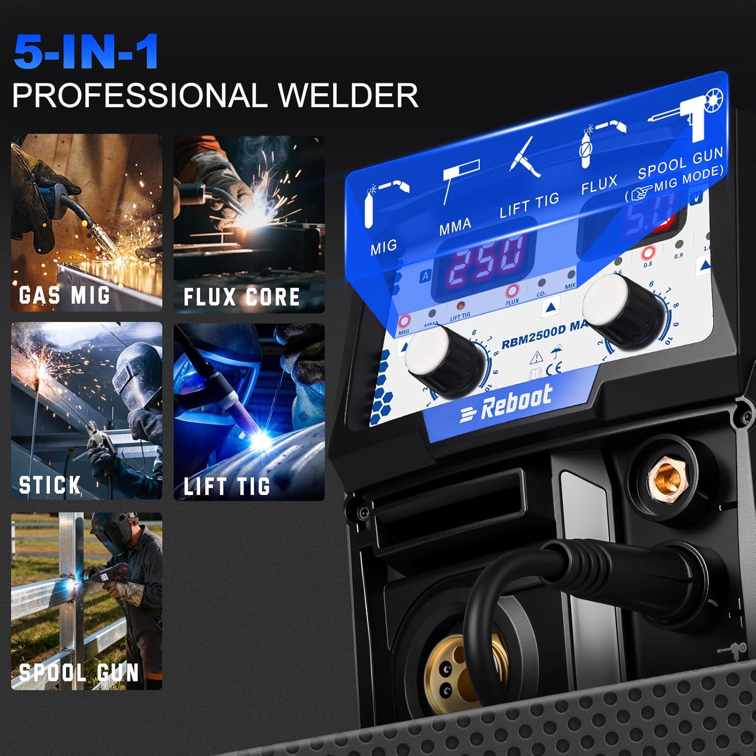
Image: The Reboot RBM2500D MAX welder highlighting its five welding processes: Gas MIG, Flux Core, Stick, Lift TIG, and Spool Gun. This illustrates the machine's versatility for various welding tasks.
4. Setup and Installation
4.1 Control Panel Introduction
Familiarize yourself with the control panel for efficient operation. The dual display provides clear and simple settings.

Image: The control panel of the Reboot RBM2500D MAX welder. Key components are numbered for identification: 1. Current display, 2. Voltage/Thrust/Post Time display, 3. Welding Modes selector, 4. Gas Selector Button, 5. Wire Diameter Button, 6. Left Value Knob, 7. Right Value Knob.
- Current Display (1): Shows the welding current in Amperes (A).
- Voltage/Thrust/Post Time Display (2): Shows the welding voltage in Volts (V), Thrust for Stick welding, or Post Time for TIG welding.
- Welding Modes (3): Selects between MIG, MMA (Stick), and Lift TIG welding processes.
- Gas Selector Button (4): Toggles between different gas types (e.g., CO2, MIX) for MIG welding or selects Flux-Cored (gasless) mode.
- Wire Diameter Button (5): Adjusts settings based on the wire diameter being used.
- Left Value Knob (6): Used to adjust the value displayed on the left screen (e.g., current).
- Right Value Knob (7): Used to adjust the value displayed on the right screen (e.g., voltage).
4.2 Connector Types
The welder is compatible with both 4-pin and 6-pin connectors for the spool gun, ensuring broad compatibility with various accessories.

Image: Various connector types for the welder. This includes a Euro Connector, a 6-Pin Male Signal Plug, and a 4Pin-6Pin Adapter, illustrating the switchable compatibility for different accessories.
- Euro Connector: Standard connection for MIG torches.
- 6-Pin Male Signal Plug: Used for connecting newer spool guns or accessories requiring a 6-pin interface.
- 4Pin-6Pin Adapter: Provides compatibility for older 4-pin accessories with the 6-pin system.
4.3 Wire Feeding Construction
Proper installation of the welding wire is crucial for consistent feeding and optimal weld quality. Follow these steps:
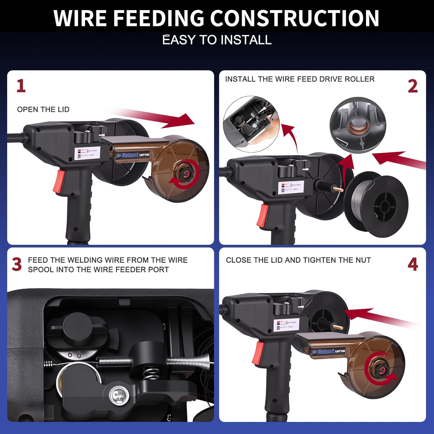
Image: A four-step visual guide for wire feeding construction. 1. Open the lid of the wire feeder. 2. Install the wire feed drive roller. 3. Feed the welding wire from the wire spool into the wire feeder port. 4. Close the lid and tighten the nut.
- Open the Lid: Open the side compartment of the wire feeder to access the spool area.
- Install the Wire Feed Drive Roller: Place the appropriate drive roller for your wire type and size onto the spindle. Ensure it is securely seated.
- Feed the Welding Wire: Mount the wire spool onto the spindle. Guide the welding wire from the spool through the tension mechanism and into the wire feeder port. Ensure the wire is properly seated in the drive roller groove.
- Close the Lid and Tighten: Close the wire feeder lid and secure any retaining nuts or latches to ensure the spool and wire are held firmly in place.
4.4 Different Rollers for Different Wire
Using the correct drive roller is essential for smooth wire feeding and preventing wire deformation. The RBM2500D MAX supports different roller types for various wire materials and diameters.

Image: Three types of drive rollers for welding wire: W Type Roller for Flux Core Wire (0.040", 0.030"), V Type Roller for Solid Wire (0.030", 0.023"), and U Type Roller for Aluminum Wire (0.040", 0.030"). Each roller is designed for specific wire types and sizes to ensure proper feeding.
- W Type Roller: Designed for Flux Core Wire, typically available in 0.030" and 0.040" diameters.
- V Type Roller: Suitable for Solid Wire, commonly used with 0.023" and 0.030" diameters.
- U Type Roller: Specifically for Aluminum Wire, available in 0.030" and 0.040" diameters.
Always match the roller type and groove size to your welding wire to prevent feeding issues.
5. Operating Instructions
5.1 General Operation Steps
- Connect Power: Plug the welder into a suitable 120V or 240V power outlet. Ensure the correct voltage is selected if applicable (auto-sensing for this model).
- Connect Ground Clamp: Attach the ground clamp securely to the workpiece or welding table, ensuring good electrical contact.
- Connect Torch/Electrode Holder: Connect the appropriate welding torch (MIG, TIG, or electrode holder for Stick) to the corresponding terminals.
- Select Welding Mode: Use the 'Welding Modes' button (3 on the panel) to select MIG, MMA (Stick), or Lift TIG.
- Adjust Parameters: Use the 'Left Value Knob' (6) and 'Right Value Knob' (7) to set the desired current, voltage, wire speed, or other parameters according to your welding process and material. Refer to welding charts for recommended settings.
- Gas Connection (MIG/TIG): If using gas-shielded welding (MIG Gas or TIG), connect the gas cylinder to the welder's gas inlet and set the flow rate on the regulator. Use the 'Gas Selector Button' (4) to select the correct gas type.
- Begin Welding: With all safety gear in place, initiate the arc and begin welding.
5.2 Spool Gun Function for Aluminum Welding
The RBM2500D MAX is compatible with a spool gun, making aluminum welding significantly easier by providing direct wire feed to the torch, reducing wire feeding issues common with soft aluminum wire.
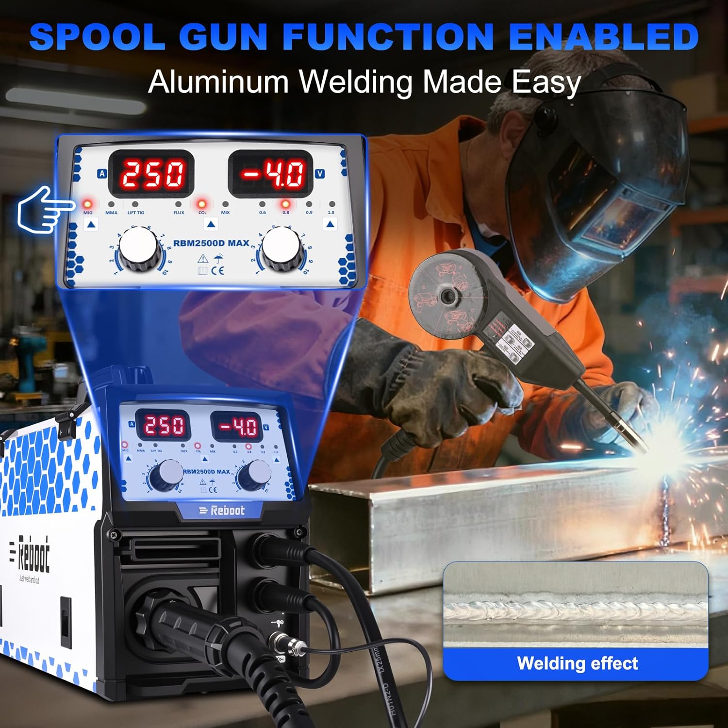
Image: The Reboot RBM2500D MAX welder with a spool gun connected, demonstrating aluminum welding. The image shows a welder operating the spool gun on an aluminum workpiece, with a close-up of the resulting weld bead, indicating effective aluminum welding capabilities.
- Connection: Connect the spool gun to the designated port on the welder. Ensure the 4-pin or 6-pin connector is securely attached.
- Wire Loading: Load the aluminum wire spool directly into the spool gun.
- Gas: Use 100% Argon shielding gas for aluminum MIG welding.
- Settings: Adjust the wire speed and voltage on the welder's control panel, or directly on the spool gun if it has controls, according to the aluminum thickness and wire diameter.
- Technique: Use a push technique for aluminum welding.
6. Maintenance
Regular maintenance ensures the longevity and optimal performance of your welder. Always disconnect the power supply before performing any maintenance.
- Cleaning: Periodically clean the welder's exterior with a dry cloth. Use compressed air to blow out dust and debris from inside the machine, especially from cooling vents, to prevent overheating.
- Torch and Cables: Inspect welding torches, cables, and ground clamps for damage, fraying, or loose connections. Replace damaged components immediately.
- Drive Rollers: Clean the drive rollers regularly to remove wire residue. Ensure the correct roller type and groove size are installed for the wire being used.
- Contact Tips and Nozzles: For MIG welding, regularly clean or replace contact tips and nozzles as they wear out or become clogged with spatter.
- Gas System: Check gas hoses and connections for leaks. Ensure the gas regulator is functioning correctly.
- Storage: Store the welder in a clean, dry environment, protected from dust and moisture.
7. Troubleshooting
This section addresses common issues you might encounter. For problems not listed here, contact customer support.
| Problem | Possible Cause | Solution |
|---|---|---|
| No power to welder | Power cord unplugged, circuit breaker tripped, faulty power switch | Check power connections, reset circuit breaker, contact support if switch is faulty |
| No arc/Poor arc starting | Poor ground connection, incorrect settings, worn contact tip (MIG), damp electrodes (Stick) | Ensure solid ground, adjust current/voltage, replace contact tip, dry electrodes |
| Wire feeding issues (MIG/Spool Gun) | Incorrect drive roller, tension too loose/tight, clogged liner, kinked wire | Install correct roller, adjust tension, clean/replace liner, straighten wire |
| Excessive spatter (MIG) | Voltage too high, wire speed too low, incorrect gas flow, dirty workpiece | Adjust voltage/wire speed, check gas flow, clean workpiece |
| Porosity in weld (MIG/TIG) | Insufficient shielding gas, gas leak, contaminated workpiece, excessive wind | Check gas supply/flow, seal leaks, clean material, use wind screens |
8. Specifications
Technical specifications for the Reboot RBM2500D MAX 180A 5-in-1 Multiprocess Welder:
- Model: RBM2500D MAX
- Input Voltage: 120V/240V Dual Voltage
- Output Current: Up to 180A (True-to-spec)
- Welding Processes: MIG (Gas), Flux-Cored (Gasless), Stick (MMA), Lift TIG, Spool Gun Compatible
- Compatibility: RBM2500 PRO system, includes 4-pin and 6-pin connectors
- Construction: Reinforced wrap-around corners for durability
- ASIN: B0G4M8P6D1
- Date First Available: September 10, 2025
9. Warranty and Support
For warranty information, technical support, or service inquiries, please refer to the warranty card included with your product or visit the official Reboot website. Keep your purchase receipt as proof of purchase for warranty claims. For direct assistance, contact Reboot customer service.


