1. Introduction
This manual provides detailed instructions for the installation, configuration, and operation of the GEPRC TAKER F722 BT 32Bit 50A STACK. This product integrates a high-performance flight controller (FC) and an electronic speed controller (ESC) into a compact unit, designed for advanced remote-controlled vehicles. Please read this manual thoroughly before use to ensure proper functionality and safety.
2. Product Overview
The GEPRC TAKER F722 BT 32Bit 50A STACK is a robust and feature-rich component for high-performance FPV drones and similar applications. It combines a powerful F722 flight controller with a 50A 4-in-1 ESC, offering precise control and efficient power delivery.

Figure 1: Assembled view of the GEPRC TAKER F722 BT 32Bit 50A STACK, showing the flight controller mounted above the ESC.
Key Features:
- Advanced STM32F722 microcontroller with ICM42688-P Gyro for precise flight control.
- Direct plug-and-play compatibility with Air Unit for streamlined setup.
- Integrated GEP-BL32 50A 32Bit ESC for robust motor control.
- Dual independent BEC (5V@3A, 9V@2.5A) for stable power supply.
- Integrated LC filter and shock-absorbing mounts to minimize vibrations and electrical noise.
- 512M onboard black box for flight data logging.
- Bluetooth support for parameter tuning via mobile application.
- Modern USB-C interface for easy firmware updates and configuration.
3. Specifications
GEP-F722-BT-HD V3 Flight Controller

Figure 2: Top view of the GEP-F722-BT-HD V3 Flight Controller, showing the MCU, USB-C port, and various connectors.
- MCU: STM32F722
- IMU: ICM42688-P (SPI)
- Air Unit Connection: Direct plug-in
- Black Box: 512M onboard
- Bluetooth: Supported
- Barometer: Supported
- USB Interface: Type-C
- OSD: BetaFlight OSD w/ AT7456E chip
- BEC: 5V@3A, 9V@2.5A dual BEC
- Firmware Target: GEPRCF722_BT_HD_V3
- Dimensions: 36.9×36.9mm, mounting holes: 30.5×30.5mm (φ4mm, reduces to φ3mm with silicone rings)
- Input Voltage: 3-6S LiPo
- UART: 5 groups (UART4 fixed for Bluetooth)
- Power Filter: Integrated LC filter
- Weight: 8.2g
GEP-BL32 50A 96K 4IN1 ESC
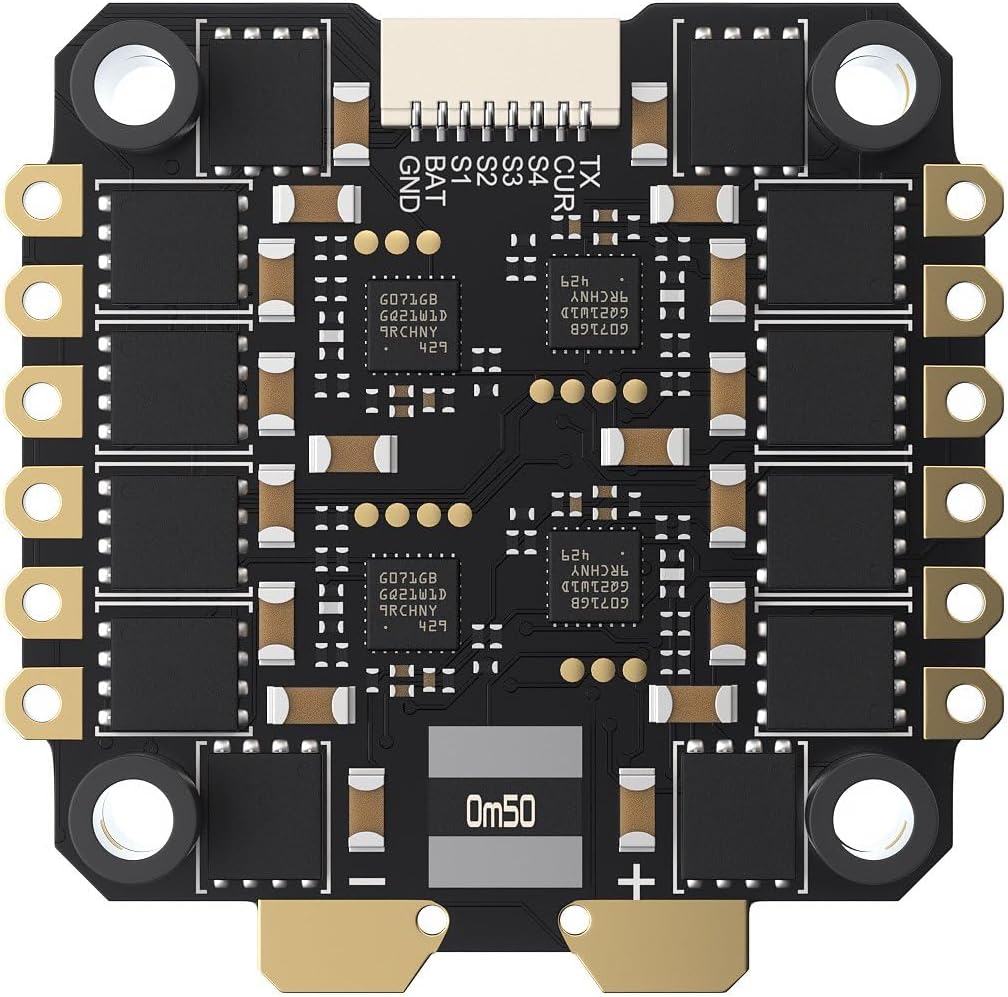
Figure 3: Bottom view of the GEP-BL32 50A 96K 4IN1 ESC, showing motor pads and power input.
- Model: GEP-BL32 50A 96K 4IN1 ESC
- Input Voltage: 3-6S Lipo
- Continuous Current: 50A
- Burst Current: 55A (5 seconds)
- Galvanometer: Supported
- Telemetry: Supported
- Supported Protocol: Dshot 150/300/600
- Dimensions: 42.5×42.1mm, mounting holes: 30.5×30.5mm
- Weight: 14g
- Target: ST_G0_05 – 31.92 (Pre-installed with BL32 test firmware; AM32 also supported, requires customer flashing)
4. Package Contents
Verify that all items listed below are included in your package:
- 1 x FC board (GEP-F722-BT-HD V3)
- 1 x ESC board (GEP-BL32 50A 96K 4IN1)
- 1 x Capacitor
- 1 x O3 3-in-1 connection cable
- 1 x FC adapter cable
- 1 x sh1.0 4pin silicone cable
- 1 x Camera connection cable
- 1 x VTX connection cable
- 1 x XT60 power cable
- 4 x M3*30 screws
- 4 x M3*25 screws
- 8 x Nylon nuts
- 12 x Silicone anti-shake pads
5. Setup and Installation
Proper installation is crucial for the performance and longevity of your flight stack. Follow these steps carefully.
5.1 Mounting the Stack
- Attach the silicone anti-shake pads to the mounting holes of the ESC board.
- Mount the ESC board onto your frame using the provided M3 screws and nylon nuts. Ensure the orientation is correct according to your frame and desired motor layout.
- Place the FC board on top of the ESC board, aligning the mounting holes. Use additional silicone pads and nuts if necessary to secure the FC.

Figure 4: Angled view of the assembled stack, highlighting the mounting points and layered design.
5.2 Wiring Diagram (General Guidance)
Refer to the specific wiring diagram provided by GEPRC for your flight controller model for precise connections. The following is general guidance:
- Power Input: Connect the XT60 power cable to the main battery pads on the ESC. Ensure correct polarity.
- Motors: Solder motor wires to the corresponding motor pads (M1-M4) on the ESC.
- Flight Controller to ESC: The FC and ESC are designed to stack and connect directly. Ensure the pin headers are correctly aligned and seated.
- Receiver: Connect your receiver (e.g., SBUS, CRSF, ELRS) to the appropriate UART on the FC. Refer to the FC's pinout for specific UART assignments.
- Video Transmitter (VTX): Connect the VTX to the designated VTX pads (Video In, 5V/9V, GND) on the FC. Use the provided VTX connection cable.
- Camera: Connect your FPV camera to the designated camera pads (Video Out, 5V, GND) on the FC. Use the provided camera connection cable.
- Air Unit: Utilize the O3 3-in-1 connection cable for direct connection to compatible Air Units.
- GPS/Other Peripherals: Connect any additional peripherals (e.g., GPS, LED strips) to available UARTs or dedicated pads as per the FC's pinout.
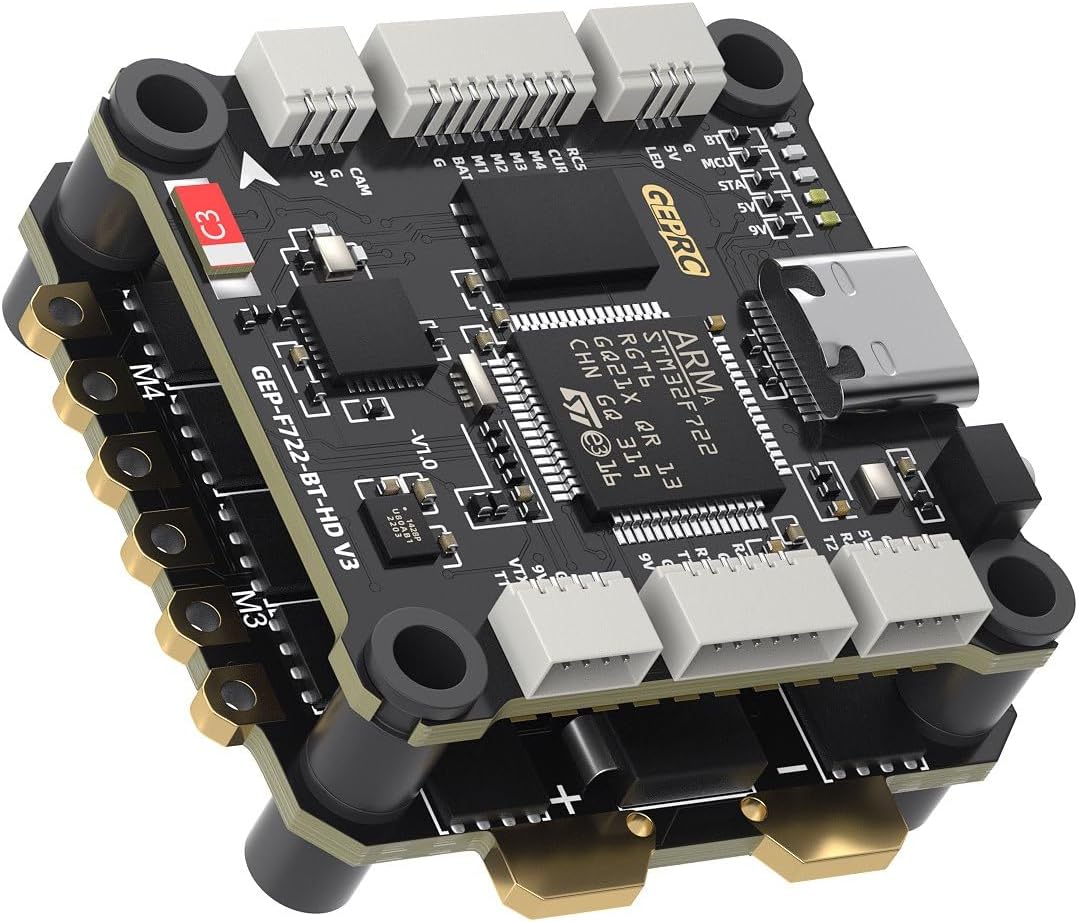
Figure 5: Another angled view of the stack, showing various connection points for peripherals.
5.3 Software Configuration (BetaFlight)
- Install BetaFlight Configurator: Download and install the latest BetaFlight Configurator software on your computer.
- Connect FC: Connect the FC to your computer using a USB-C cable.
- Flash Firmware: If necessary, flash the recommended firmware target (GEPRCF722_BT_HD_V3) using the BetaFlight Configurator.
- Initial Setup: Follow the initial setup wizard in BetaFlight Configurator.
- Configuration:
- Configure UARTs for your receiver, VTX, GPS, etc.
- Set up your motor protocol (Dshot600 recommended).
- Calibrate accelerometer and gyroscope.
- Configure OSD settings.
- Adjust PID tuning and rates as desired.
- ESC Configuration: The ESC comes pre-installed with BL32 test firmware. For advanced configuration or flashing AM32 firmware, use a compatible ESC configurator tool.
- Bluetooth Tuning: Download the GEPRC Connect app (or similar compatible app) on your mobile device to connect via Bluetooth for parameter tuning.
6. Operating Instructions
Once the GEPRC TAKER F722 BT 32Bit 50A STACK is correctly installed and configured, follow these general operating guidelines:
- Pre-Flight Check: Before each flight, ensure all connections are secure, propellers are correctly installed, and the battery is fully charged.
- Power On: Connect the LiPo battery to the XT60 connector. The FC and ESC will power on, and indicator LEDs will illuminate.
- Arming: Arm your drone using the designated switch on your remote controller. Ensure you are in a safe environment with sufficient space.
- Flight: Operate your drone according to your skill level and local regulations.
- Disarming: Disarm your drone after landing using the designated switch.
- Power Off: Disconnect the LiPo battery immediately after disarming.
Safety Note: Always remove propellers before connecting to a computer or performing any maintenance to prevent accidental motor activation.
7. Maintenance
Regular maintenance helps ensure the longevity and reliable performance of your flight stack.
- Visual Inspection: Periodically inspect the FC and ESC for any signs of damage, loose connections, or burnt components.
- Cleaning: Gently clean any dust or debris from the boards using compressed air or a soft brush. Avoid using liquids.
- Firmware Updates: Check the official GEPRC website for the latest firmware updates for both the FC and ESC. Keeping firmware updated can improve performance and add new features.
- Connection Integrity: Ensure all soldered joints are solid and all connectors are securely seated.
8. Troubleshooting
If you encounter issues, refer to the following common troubleshooting steps:
- No Power:
- Check battery connection and voltage.
- Verify XT60 polarity and solder joints.
- Inspect for any short circuits on the board.
- Motors Not Spinning:
- Ensure motors are correctly soldered to the ESC.
- Check motor direction in BetaFlight Configurator.
- Verify ESC protocol settings (Dshot).
- Confirm the drone is armed and throttle is above minimum.
- No Receiver Input:
- Check receiver wiring to the FC (signal, 5V, GND).
- Verify UART configuration in BetaFlight for the receiver.
- Ensure receiver is bound to your radio transmitter.
- FC Not Connecting to BetaFlight:
- Ensure correct USB-C cable is used (data capable).
- Install necessary VCP drivers (ImpulseRC Driver Fixer can help).
- Try a different USB port or computer.
For further assistance, consult the GEPRC official support channels or community forums.
9. Warranty and Support
Warranty information for the GEPRC TAKER F722 BT 32Bit 50A STACK is typically provided by the manufacturer or the point of purchase. Please retain your proof of purchase for warranty claims.
For technical support, firmware downloads, and additional resources, please visit the official GEPRC website or contact their customer service directly. Community forums and online resources dedicated to FPV electronics can also be valuable sources of information and peer support.


