1. Introduction
This manual provides detailed instructions for the installation, operation, and maintenance of your SINOTIMER DC/AC 24V Digital Programmable Timer Switch, Model 24VDC. This device is designed for precise, programmable control of electrical circuits, offering up to 28 ON/OFF events per day across a 7-day cycle. Please read this manual thoroughly before use to ensure proper function and safety.

Image 1.1: The SINOTIMER 7 Day Digital Programmable Timer Switch.
2. Safety Information
- Electrical Hazard: Installation and wiring should only be performed by qualified personnel. Ensure power is disconnected before any installation or maintenance.
- Voltage Compatibility: This device operates on DC/AC 24V. Connecting to an incorrect voltage supply may damage the unit and pose a safety risk.
- Load Capacity: Do not exceed the maximum load rating of 10A at 250VAC (2000 watts). For higher loads, use an external contactor or relay.
- Environment: Install the timer in a dry, protected environment. While the unit has some dustproof features, direct exposure to water or extreme temperatures should be avoided.
- Battery: The internal battery is for memory backup only. Do not attempt to charge or replace it unless specified in the maintenance section.
3. Package Contents
Verify that all items are present in the package:
- 1x SINOTIMER Digital Programmable Timer Switch (Model: 24VDC)
- 1x Mounting Bracket
- 1x Dust Cover
- 1x CR2032 Battery (pre-installed or separate)
- 1x Disassembly Tool (small screwdriver)
- 2x Mounting Screws
- 5x Spade Connecting Wires
- 1x User Manual (this document)
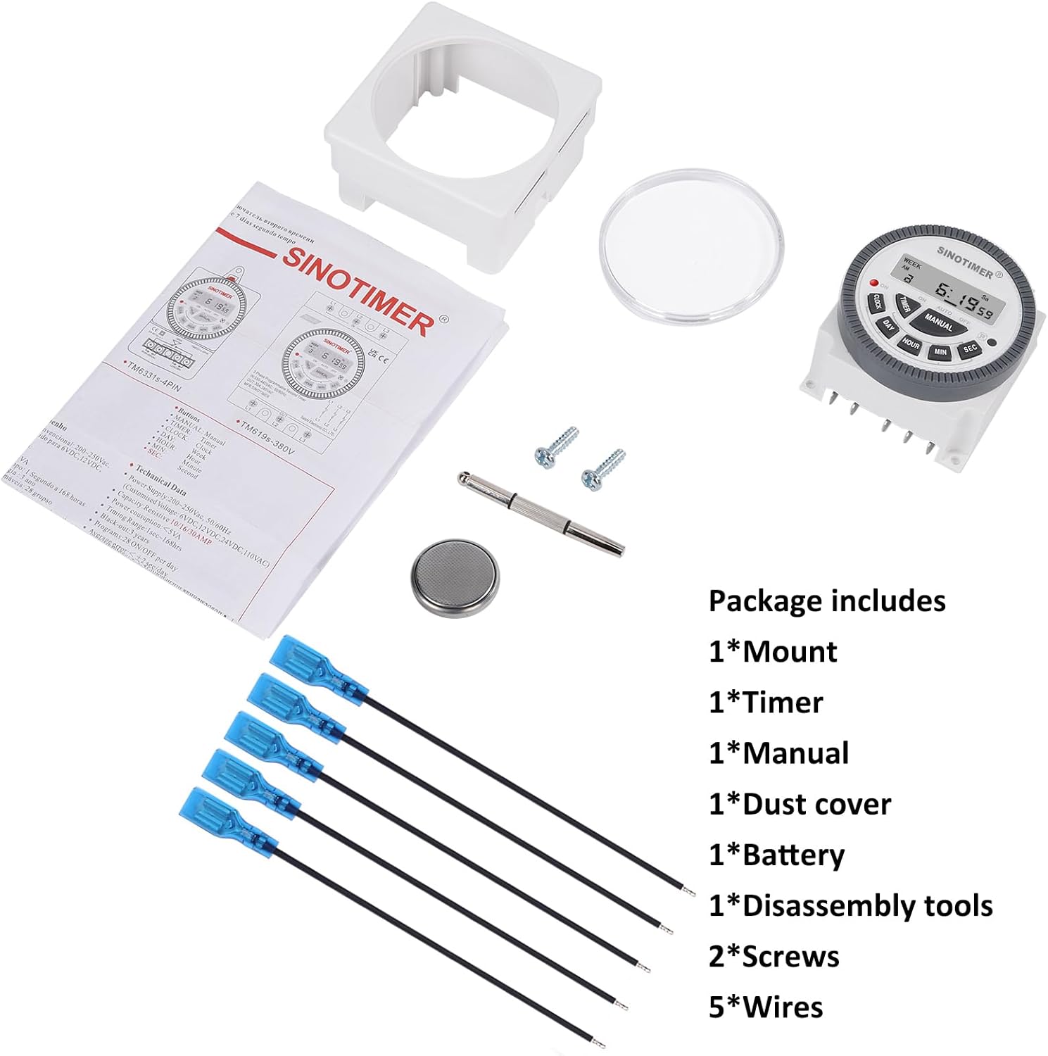
Image 3.1: Visual representation of the package contents, including the timer, mount, manual, dust cover, battery, disassembly tool, screws, and wires.
4. Product Overview & Features
The SINOTIMER DC/AC 24V Digital Programmable Timer Switch is a versatile device designed for automating various electrical applications. Its compact design and digital display ensure ease of use and integration into control panels.
Key Features:
- 7-Day Programmability: Allows for up to 28 ON/OFF events per day, with flexible programming blocks for daily, weekly, or custom schedules.
- Digital Display: Clear LCD for time, day, and program status.
- Internal Battery Backup: Retains program settings during power outages.
- SPDT Output: Single Pole Double Throw relay output (1 Normally Open + 1 Normally Closed contact).
- High Load Capacity: Rated for up to 10A at 250VAC, 2000 watts.
- 12/24 Hour Format: User-selectable time display format.
- Dustproof Design: Enhanced durability for various environments.

Image 4.1: Overview of the timer's key features, including its robust design and advanced functionality.
5. Specifications
| Feature | Specification |
|---|---|
| Model | 24VDC (TM-619) |
| Input Voltage | DC/AC 24V |
| Output Type | SPDT (1NO+1NC) |
| Max Load Current | 10A @ 250VAC, 2000W |
| Programmable Events | Up to 28 ON/OFF per day |
| Time Format | 12-hour / 24-hour selectable |
| Battery Backup | Internal CR2032 (for program memory) |
| Dimensions (D x W x H) | 1.77" x 2.83" x 2.83" (45mm x 72mm x 72mm) |
| Weight | 5.3 ounces (approx. 150g) |
| Material | Metal, Plastic |

Image 5.1: Dimensional drawing and terminal layout of the timer switch.
6. Installation & Wiring
WARNING: Disconnect all power before installation to prevent electric shock or equipment damage.
6.1 Mounting
- Select a suitable location for mounting, ensuring it is protected from moisture and excessive heat.
- Attach the mounting bracket to a flat surface using the provided screws.
- Slide the timer switch into the mounting bracket until it clicks securely into place.
- Optionally, install the clear dust cover over the timer face for added protection.
6.2 Wiring Instructions
The timer switch features 5 spade connecting terminals. Refer to the wiring diagram below and the labels on the back of the unit for correct connections.
- Terminals 1 & 2: Power Input (DC/AC 24V). Connect your 24V power supply here.
- Terminal 3: Common (COM) for the relay output.
- Terminal 4: Normally Open (NO) contact for the relay output. The circuit connected here will be ON when the timer is active.
- Terminal 5: Normally Closed (NC) contact for the relay output. The circuit connected here will be OFF when the timer is active.

Image 6.1: Simplified wiring diagram for the timer switch.

Image 6.2: Example of spade connectors attached to the timer terminals.
7. Operating Instructions
After successful installation and power connection, the timer display should illuminate. If not, ensure power is supplied correctly and the internal battery is properly seated.
7.1 Initial Setup (First Use)
- Reset: Press the 'R' (Reset) button with a pointed object (e.g., the provided disassembly tool) to clear all previous settings. The display will show '0:00'.
- Set Current Time:
- Press the CLOCK button.
- Press DAY to select the current day of the week (Mo, Tu, We, Th, Fr, Sa, Su).
- Press HOUR to set the current hour.
- Press MIN to set the current minute.
- Press SEC to set the current second (optional, for precise synchronization).
- To switch between 12-hour (AM/PM) and 24-hour format, press CLOCK and DAY simultaneously.
7.2 Programming ON/OFF Events
The timer supports up to 28 ON/OFF programs. Each program consists of an ON time and an OFF time.
- Press the TIMER button. The display will show '1 ON'. This is the first ON program.
- Press DAY to select the day(s) for this program. You can choose a single day, weekdays, weekends, or various combinations. Keep pressing DAY to cycle through options.
- Press HOUR to set the desired ON hour.
- Press MIN to set the desired ON minute.
- Press TIMER again. The display will show '1 OFF'. This is the first OFF program.
- Repeat steps 2-4 to set the desired OFF day(s), hour, and minute for this program.
- Continue pressing TIMER to cycle through '2 ON', '2 OFF', up to '28 ON', '28 OFF', setting each program as needed.
- After setting all desired programs, press the CLOCK button to return to the current time display. The programs are now saved.
7.3 Manual Override
The MANUAL button allows you to override the programmed schedule temporarily or permanently.
- Press MANUAL to cycle through the following modes:
- ON: Output is continuously ON, ignoring programs.
- AUTO ON: Output is currently ON, following programs.
- AUTO OFF: Output is currently OFF, following programs.
- OFF: Output is continuously OFF, ignoring programs.
- Select AUTO ON or AUTO OFF to resume programmed operation.
8. Maintenance
8.1 Cleaning
Wipe the unit with a soft, dry cloth. Do not use abrasive cleaners or solvents.
8.2 Battery Replacement
The internal CR2032 battery provides backup for program memory. If the display becomes dim or programs are lost during power outages, the battery may need replacement.
- WARNING: Disconnect main power to the timer before replacing the battery.
- Locate the battery compartment on the back of the unit.
- Carefully open the compartment cover.
- Remove the old CR2032 battery and insert a new one, ensuring correct polarity (+ side up).
- Close the battery compartment cover.
- After replacement, perform an initial setup (Section 7.1) to reset and set the current time.

Image 8.1: Location of the replaceable CR2032 battery.
9. Troubleshooting
| Problem | Possible Cause | Solution |
|---|---|---|
| Display is blank or dim | No power supply; Incorrect wiring; Dead internal battery. | Check 24V power input (Terminals 1 & 2). Verify wiring. Replace CR2032 battery. |
| Programs are not running | Timer is in Manual ON/OFF mode; Incorrect program settings; Incorrect current time. | Press MANUAL until 'AUTO ON' or 'AUTO OFF' is displayed. Review program settings (Section 7.2). Set current time correctly (Section 7.1). |
| Output does not switch ON/OFF | Incorrect output wiring; Load exceeds capacity; Faulty relay. | Verify output wiring (Terminals 3, 4, 5) to your load. Ensure load does not exceed 10A/2000W. If issues persist, contact support. |
| Time is inaccurate | Internal clock drift; Battery low. | Reset and set time again. Consider replacing the internal battery if drift is significant. |
10. Warranty & Support
For warranty information and technical support, please refer to the documentation provided with your purchase or contact SINOTIMER customer service through the retailer where the product was purchased. Please have your product model (24VDC) and purchase date available when contacting support.
Online Resources: For additional information, FAQs, or to view other SINOTIMER products, visit the official SINOTIMER store or website.


