
1. Introduction
This manual provides essential information for the installation, operation, and maintenance of your Beninca K MB 24 USA Electromechanical 24VDC Post Mounting Articulated Arm Kit. Please read this manual carefully before proceeding with any installation or operation to ensure safe and efficient use of the product. Keep this manual for future reference.
2. Product Overview and Components
The Beninca K MB 24 USA kit is a robust electromechanical system designed for automating swing gates, particularly suitable for gates with large columns. It features 24Vdc motors for intensive use and enhanced safety.

Image: Overview of the Beninca K MB 24 USA kit, showing the electromechanical actuator, articulated arm, control panel, and remote controls.
Kit Contents:
- 2 x Electromechanical Actuators MB 24 (24Vdc Motor)
- 2 x Articulated Arms BA
- 1 x Control Panel / Receiver BRAINY 24 with Radio-Receiver
- 2 x Beninca Long-Range 2 Button ARE 128 Remote Controls

Image: Close-up view of the Beninca Articulated Arm BA, a key component for gate movement.
3. Features
- Articulated arm design, suitable for large gate posts.
- 24Vdc actuator for intensive use, ensuring durability and performance.
- Amperometric anti-crushing control (with BRAINY24 control panel) for enhanced safety.
- Smooth and precise gate movement.
- Compact and aesthetically pleasing design.
- Weather-resistant plastic cover for outdoor durability.
- Aluminum gear-box with grease lubrication for reliable operation.
- Adjustable positive stops (BN 24) for precise gate positioning.
- Adjustable limit-switches (MB & PR) for accurate travel limits.
- Quick manual release mechanism for emergency operation.
4. Setup and Installation
Installation of the Beninca K MB 24 USA kit requires technical expertise. It is highly recommended that installation be performed by qualified personnel to ensure proper functioning, safety, and compliance with local regulations.
Key Installation Considerations:
- Gate Preparation: Ensure the gate structure is sound, moves freely, and is properly hinged.
- Actuator Mounting: Mount the actuators securely to the gate posts and gate leaves according to the provided templates and measurements. Proper alignment is crucial for smooth operation.
- Control Panel Wiring: Connect the actuators, safety devices, and power supply to the BRAINY 24 control panel. Refer to the detailed wiring diagrams provided in the separate technical manual for the control panel.
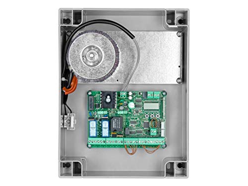
Image: Internal view of the BRAINY 24 Control Panel, showing the circuit board and wiring terminals.
- Limit Switch Adjustment: Precisely adjust the mechanical and/or electronic limit switches to define the gate's open and closed positions.
- Safety Devices: Install and connect all necessary safety devices, such as photocells and safety edges, to prevent crushing or entrapment.
- Remote Control Programming: Program the ARE 128 remote controls to the BRAINY 24 receiver following the control panel's instructions.
5. Operating Instructions
Once installed and configured, the Beninca K MB 24 USA gate opener is designed for user-friendly operation.
Standard Operation:
- Remote Control: Pressing a programmed button on the ARE 128 remote control will activate the gate. A single press typically initiates an open or close cycle, or stops the gate if it is in motion.
- Automatic Closing: The BRAINY 24 control panel can be configured for automatic closing after a set time, provided safety devices are active.
- Safety Features: The amperometric anti-crushing system will detect obstacles and reverse the gate's direction or stop it to prevent injury or damage.
Manual Release:
In case of power failure or malfunction, the gate can be operated manually using the quick manual release mechanism on the actuators. Consult the actuator's specific instructions for the release procedure.
6. Maintenance
Regular maintenance is crucial to ensure the longevity, reliability, and safe operation of your Beninca gate opener system.
Recommended Maintenance Schedule:
- Monthly:
- Inspect the gate's mechanical condition: hinges, wheels (if applicable), and general movement. Ensure no obstructions are present in the gate's path.
- Check the articulated arms for any signs of wear, damage, or loose connections.
- Test all safety devices (photocells, safety edges) to ensure they are functioning correctly.
- Every 6 Months:
- Clean the actuators and control panel housing.
- Check electrical connections for corrosion or looseness.
- Inspect the aluminum gear-box for proper grease lubrication. Re-lubricate if necessary, using appropriate grease as specified by Beninca.
- Verify the proper functioning of the manual release mechanism.
- Annually:
- Have a qualified technician perform a comprehensive inspection and service of the entire system.
7. Troubleshooting
This section provides general guidance for common issues. For complex problems, contact a qualified technician.
| Problem | Possible Cause | Solution |
|---|---|---|
| Gate does not move | No power; Remote control battery low; Safety devices obstructed; Motor overload. | Check power supply; Replace remote battery; Clear safety device path; Allow motor to cool down. |
| Gate opens but does not close | Safety devices obstructed or misaligned; Automatic closing disabled. | Clear safety device path, clean lenses, or realign; Check control panel settings for automatic closing. |
| Gate stops unexpectedly | Obstruction detected by anti-crushing system; Loose wiring; Motor issue. | Remove obstruction; Check wiring connections; Consult technician for motor diagnosis. |
| Remote control not working | Battery dead; Not programmed; Out of range. | Replace battery; Reprogram remote; Move closer to receiver. |
8. Specifications
Technical specifications for the Beninca K MB 24 USA Electromechanical Actuator:
| Parameter | Value |
|---|---|
| Input Voltage | 24 Vdc (from control panel BRAINY 24) |
| Current | 6 Amp |
| Torque | 200 Nm |
| Time for 90° Opening | 10 sec |
| Max Cycles | 200/day |
| Max Gate Weight (per leaf) | 400 lb |
| Max Gate Length (per leaf) | 7 Ft (as per product description) / 8 Ft (as per image) |
| Max Gate Offset | 8" |
| Actuator Weight | 20 lb |
Note: Specifications are subject to change without notice. Always refer to the latest technical documentation from Beninca.
9. Safety Information
Automated gate systems can pose significant safety risks if not installed, operated, and maintained correctly. Adhere to all safety guidelines to prevent accidents.
- Never allow children to play near the gate or with the remote controls.
- Keep the gate area clear of obstructions.
- Do not attempt to walk or drive through the gate while it is in motion.
- Ensure all safety devices (photocells, safety edges) are installed and regularly tested.
- In case of emergency, use the manual release to open the gate.
- Only qualified personnel should perform installation, repairs, or complex maintenance.
10. Support and Warranty
For technical support, spare parts, or warranty inquiries, please contact your authorized Beninca dealer or the manufacturer directly. Retain your proof of purchase for warranty claims.
Manufacturer: Beninca
Please refer to the official Beninca website or your purchase documentation for the most up-to-date contact information and warranty terms.


