1. Introduction
This manual provides detailed instructions for the installation, operation, and maintenance of the UHPPOTE Normal Closed Wired Screw-Terminal Surface-Mount Magnetic Contact. This device is designed to enhance security by detecting the opening of windows or doors, integrating seamlessly with various access control and burglar alarm systems. It operates on the principle of a Normally Closed (NC) circuit, meaning the circuit is conductive when the magnet and switch are together, and breaks when they separate.

Image: Examples of magnetic contact sensor applications on doors, windows, and safes.
2. Safety Information
Please read and understand all safety instructions before installing or operating this product. Failure to follow these instructions may result in electric shock, fire, or other hazards.
- This product is designed to work with an alarm system and cannot be connected directly to power.
- Ensure the working current is under 12V.
- Disconnect power to the alarm system before installation or maintenance to prevent electrical hazards.
- Do not expose the device to extreme temperatures or moisture.
- Keep out of reach of children.
- Only use specified tools for installation.
3. Product Overview
The UHPPOTE magnetic contact consists of two main components: a switch unit and a magnet unit. These units are designed to be mounted on a door/window frame and the door/window itself, respectively. When the door/window is closed, the two units are in close proximity, completing the circuit. When the door/window opens, the units separate, breaking the circuit and triggering the alarm system.

Image: The two components of the magnetic contact sensor.
The switch unit features screw terminals for wired connection to your alarm system. The magnet unit contains a permanent magnet. Both units are surface-mountable.
4. Specifications
| Switch Type | NC (Normally Closed) |
| Contact Type | Reed Switch |
| Operating Voltage | Under 12V DC (Max 100V DC) |
| Material | Acrylonitrile Butadiene Styrene (ABS) |
| International Protection Rating | IP65 |
| Certification | UL |
| Item Dimensions (L x W x H) | 5.1 x 1 x 0.7 cm (approx. 2 x 0.39 x 0.28 inches) |

Image: Detailed dimensions of the magnetic contact switch and magnet components.
5. Setup & Installation
Follow these steps to properly install your magnetic contact sensor:
- Prepare the Surface: Ensure the mounting surfaces on the door/window frame and the door/window itself are clean, dry, and smooth.
- Identify Components: The larger unit with screw terminals is the switch. The smaller, sealed unit is the magnet.
- Positioning: Mount the switch unit on the stationary part (door/window frame) and the magnet unit on the moving part (door/window). Ensure they are aligned horizontally or vertically and are in close proximity when the door/window is closed. The gap between the two units should be minimal for proper operation.
- Wiring (Switch Unit):Connect the two wires from your alarm system to the screw terminals on the switch unit. Use a small screwdriver to loosen the screws, insert the wires, and then tighten the screws to secure the connection. This is a Normally Closed (NC) contact, so it will complete a circuit when closed and break it when opened.

Image: Wiring terminals on the switch unit.
- Mounting Options:
- Screw Mounting: Use the provided screws to securely attach both the switch and magnet units to their respective surfaces through the pre-drilled holes.
- Adhesive Mounting: For surfaces where screws are not suitable, use strong double-sided adhesive tape (not always included) to attach the units. Ensure the surfaces are thoroughly cleaned before applying the tape for maximum adhesion.
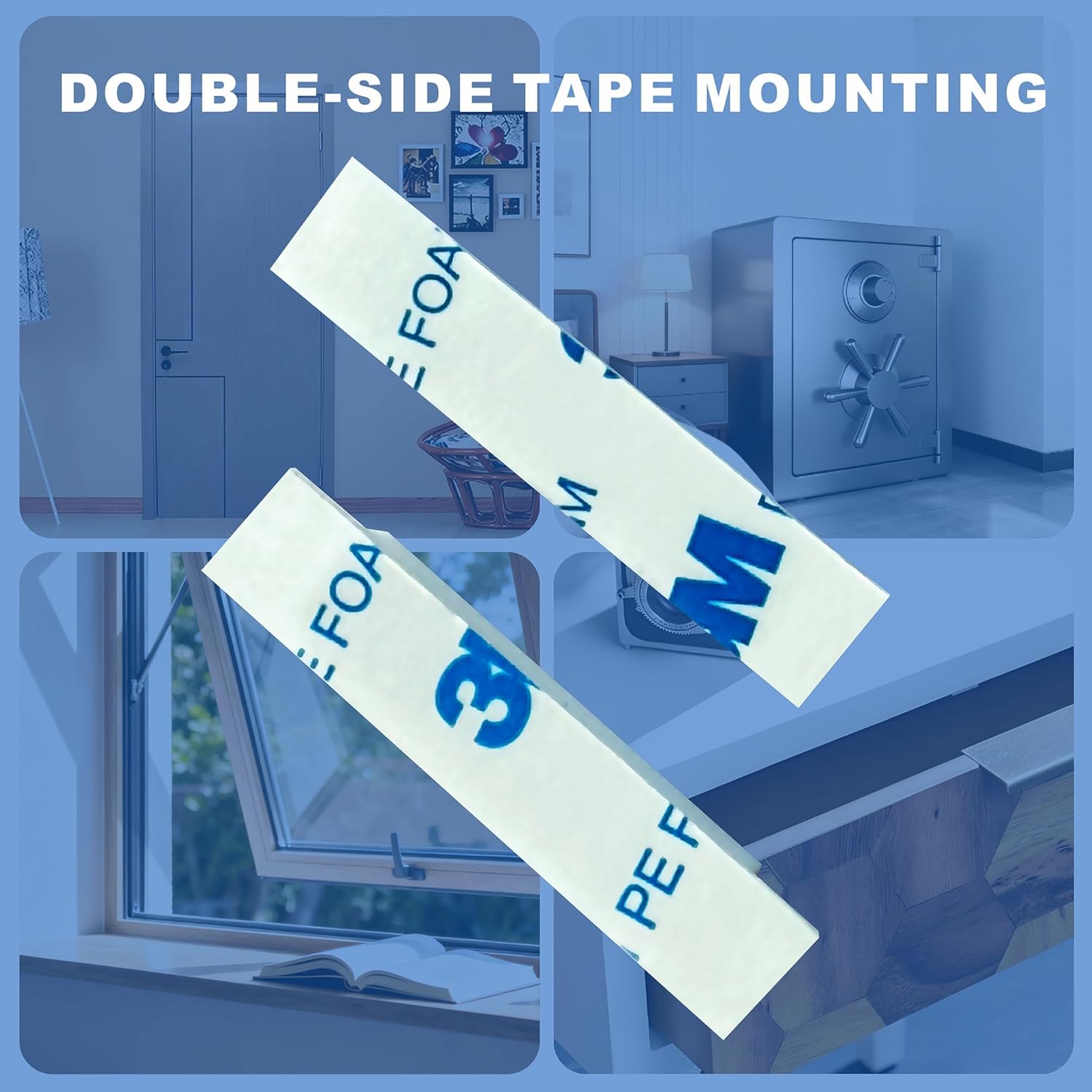
Image: Double-sided tape for adhesive mounting.
- Test Operation: After installation, test the sensor by opening and closing the door/window to ensure it triggers your alarm system correctly.
6. Operating Instructions
The UHPPOTE magnetic contact operates as a Normally Closed (NC) switch. Understanding this principle is crucial for proper integration with your alarm system.
- Normally Closed (NC): When the magnet unit and the switch unit are in close proximity (e.g., door/window is closed), the internal reed switch is closed, completing the electrical circuit.
- Circuit Open: When the magnet unit separates from the switch unit (e.g., door/window is opened), the internal reed switch opens, breaking the electrical circuit. This change in circuit state is detected by your connected alarm system, triggering an alert.

Image: Diagram showing the difference between Normally Closed (NC) and Normally Open (NO) contacts. This product is NC.
Ensure your alarm system is configured to recognize a break in the circuit as an alarm condition for NC contacts.
7. Maintenance
The UHPPOTE magnetic contact is designed for low maintenance. Regular checks can ensure its continued reliability:
- Cleaning: Periodically wipe the units with a soft, dry cloth to remove dust and dirt. Do not use abrasive cleaners or solvents.
- Alignment Check: Ensure the switch and magnet units remain properly aligned and in close proximity when the door/window is closed. If they shift, re-align and re-secure them.
- Wiring Inspection: Occasionally check the wiring connections at the screw terminals for any signs of corrosion or looseness. Tighten if necessary.
- Functionality Test: Test the sensor's operation with your alarm system regularly (e.g., monthly) to confirm it is functioning correctly.
8. Troubleshooting
If you encounter issues with your magnetic contact, refer to the following common problems and solutions:
- Sensor not triggering alarm when door/window opens:
- Check alignment: Ensure the magnet and switch units are closely aligned when the door/window is closed and separate sufficiently when opened.
- Inspect wiring: Verify that wires are securely connected to the screw terminals and there are no breaks in the wiring.
- Confirm NC configuration: Ensure your alarm system is configured for Normally Closed (NC) contacts.
- Test with multimeter: If possible, use a multimeter to check continuity across the switch terminals when the magnet is present (should show continuity) and absent (should show open circuit).
- False alarms:
- Check for loose mounting: Ensure both units are firmly attached and not shifting, which could cause intermittent contact.
- Verify magnet strength: Ensure the magnet is strong enough to keep the reed switch closed when the door/window is shut.
- Environmental factors: Strong electromagnetic interference nearby could potentially affect operation, though rare.
- Physical damage:
- If either unit is cracked or broken, it may need replacement.
9. Warranty & Support
For warranty information or technical support, please refer to the documentation provided with your purchase or contact UHPPOTE customer service through their official website or the retailer from whom the product was purchased. Please have your product model number and purchase date available when contacting support.
Model: Wired Screw-Terminal Surface-Mount Magnetic Contact
Brand: UHPPOTE


