1. Introduction
This manual provides detailed instructions for the installation, operation, and maintenance of the Avaya IP Office 500 EXP MOD Phone 30 Module. This module expands the capacity of your Avaya IP Office 500 system by adding 30 additional phone ports.
Please read this manual thoroughly before attempting to install or operate the device to ensure proper functionality and to prevent damage.
2. Safety Information
- Always use the provided or an approved AC adapter. Refer to the device label for correct voltage and current specifications.
- Do not expose the device to moisture, extreme temperatures, or direct sunlight.
- Ensure proper ventilation around the module to prevent overheating.
- Do not attempt to open or repair the device yourself. Refer all servicing to qualified personnel.
- Keep the device away from strong electromagnetic fields.
3. Package Contents
Verify that all items are present in your package:
- Avaya IP Office 500 EXP MOD Phone 30 Module (PN: 700426224)
- AC Adapter
- Power Cord
- This User Manual

Figure 3.1: Included AC adapter and power cord. The AC adapter converts wall power to the required DC voltage for the module.
4. Product Overview
The Avaya IP Office 500 EXP MOD Phone 30 is a hardware module designed to integrate seamlessly with the Avaya IP Office 500 system, providing additional connectivity for 30 corded telephones.
4.1 Front Panel
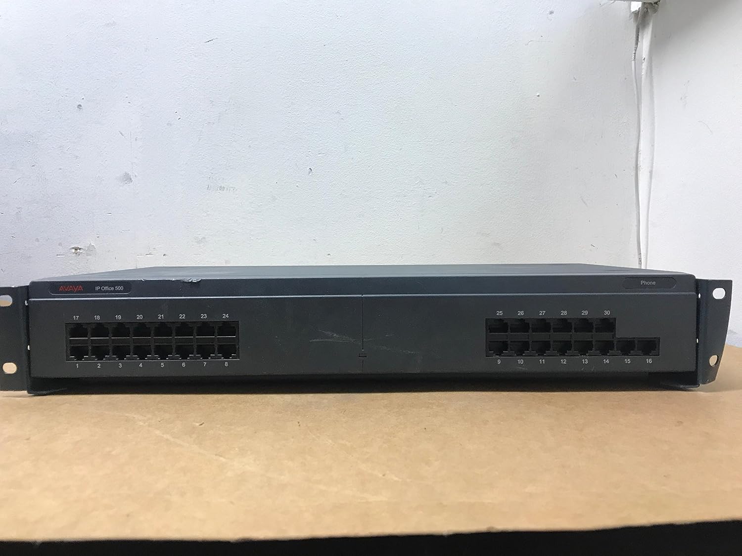
Figure 4.1: Front view of the Avaya IP Office 500 EXP MOD Phone 30 Module. It features 30 RJ11 ports for connecting analog or digital phones, arranged in two banks of 15 ports each.
- Phone Ports (1-30): RJ11 ports for connecting corded telephones. These ports are numbered for easy identification and management.
- Status Indicator Light: A small LED light (typically on the right side) indicates the operational status of the module. A green light usually signifies normal operation.
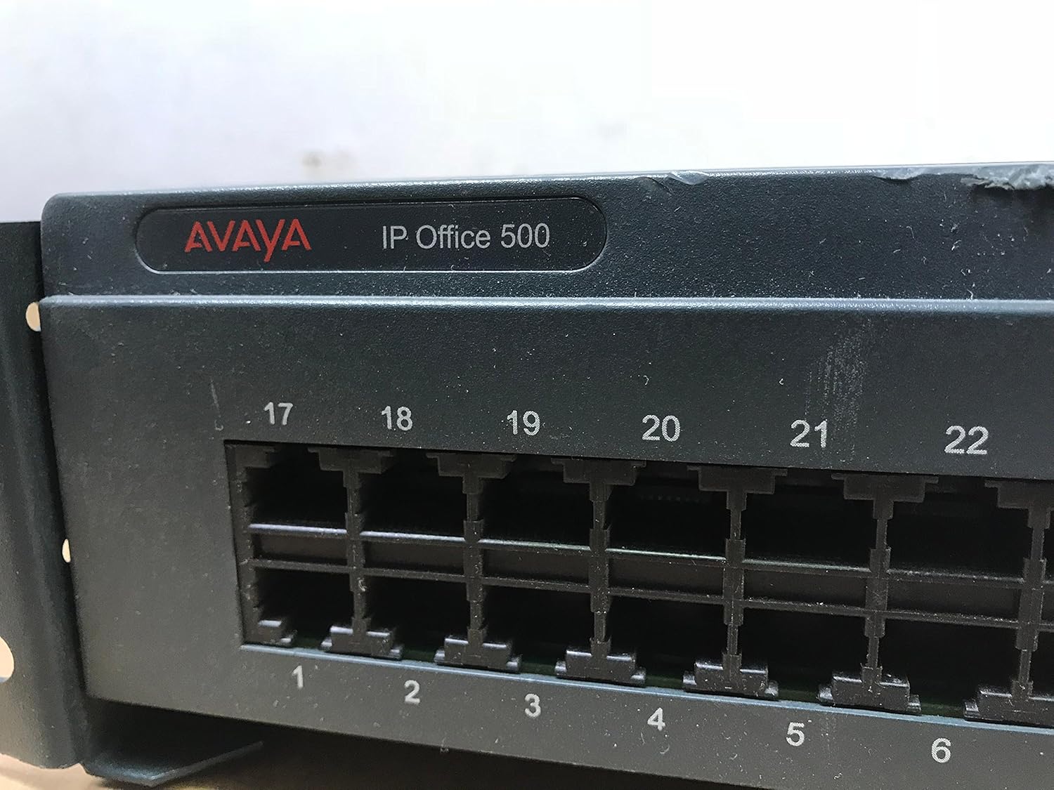
Figure 4.2: Close-up view of the left bank of phone ports (1-16) on the front panel, showing the individual RJ11 connectors and their numbering.

Figure 4.3: Close-up view of the right bank of phone ports (17-30) on the front panel, detailing the RJ11 connectors and their numbering.
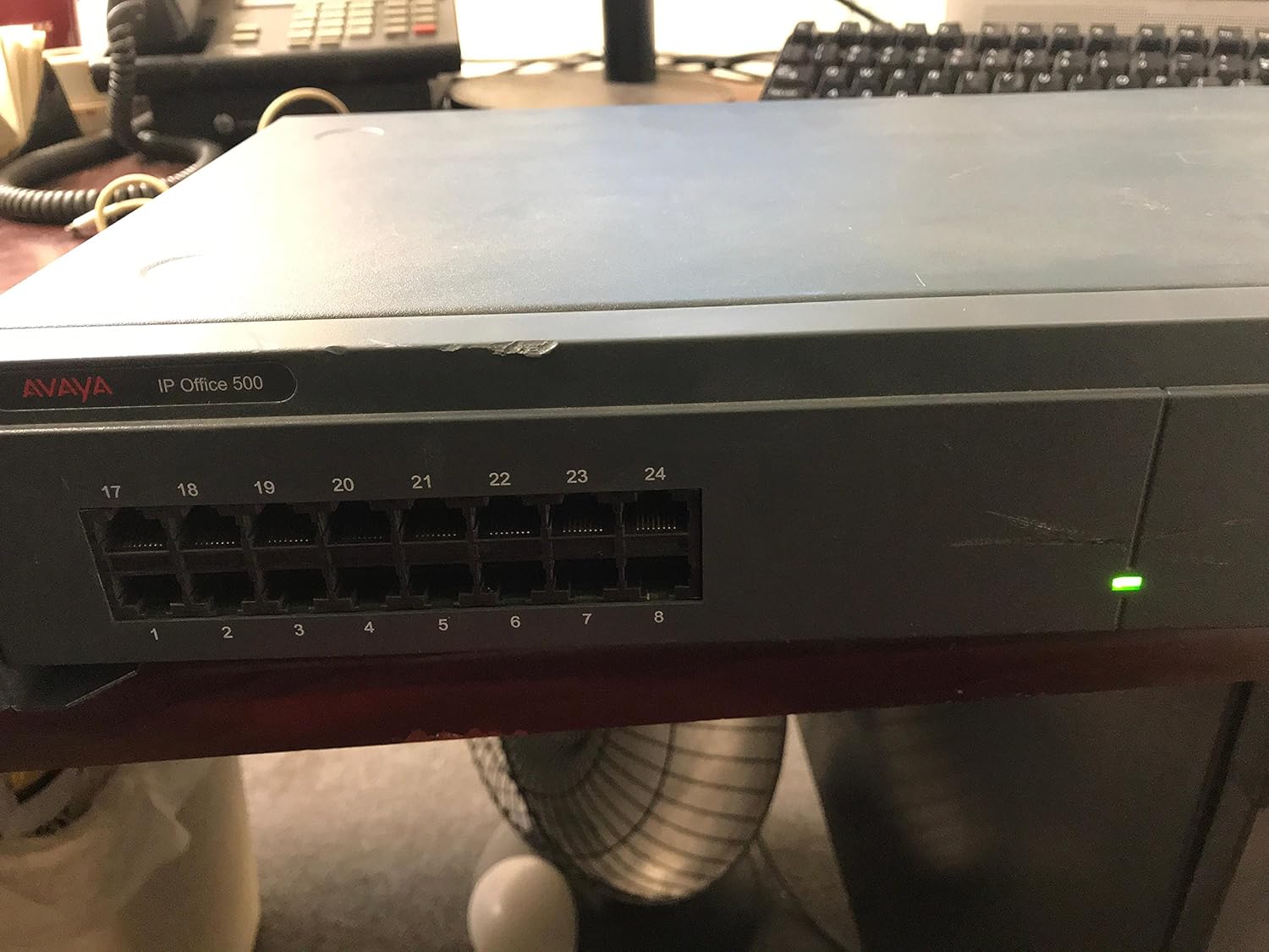
Figure 4.4: The module with its green status indicator light illuminated, signifying that the device is powered on and operating correctly.
4.2 Rear Panel

Figure 4.5: Rear view of the Avaya IP Office 500 EXP MOD Phone 30 Module, highlighting the power input, DTE port, and expansion port.
- DC I/P (Power Input): Connector for the AC adapter. Accepts 16-24V DC, 5.0A MAX for Digital Station V2, or 24V DC, 1.5A for Phone V2.
- DTE Port: A DB9 serial port, typically used for console access or diagnostic purposes.
- Expansion Port: An RJ45 port used to connect the module to the main Avaya IP Office 500 control unit or other expansion modules.
- Product Label: Contains important information such as the Avaya ID (700426224), Serial Number (08FC19401939), and compliance markings.

Figure 4.6: Detailed view of the DC power input and DTE serial port on the rear panel. Note the power specifications printed next to the DC input.

Figure 4.7: Close-up of the RJ45 Expansion port, used for connecting the module to the Avaya IP Office 500 system.
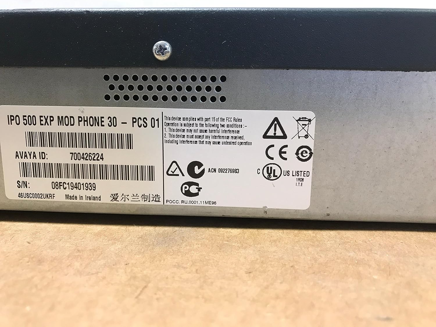
Figure 4.8: Detailed view of the product label, showing the Avaya ID: 700426224 and Serial Number: 08FC19401939, along with regulatory compliance information.
5. Setup and Installation
Follow these steps to properly install your Avaya IP Office 500 EXP MOD Phone 30 Module:
- Power Off Main System: Before connecting any expansion modules, ensure your Avaya IP Office 500 control unit is powered off and disconnected from its power source.
- Mounting (Optional): If rack-mounting, secure the module in your equipment rack using appropriate mounting hardware (not included).
- Connect Expansion Cable: Connect one end of an appropriate expansion cable (not included) to the Expansion Port on the rear of the Phone 30 module. Connect the other end to an available expansion port on your Avaya IP Office 500 control unit or another expansion module.
- Connect Phones: Connect your corded telephones to the numbered Phone Ports (1-30) on the front panel of the module using standard RJ11 phone cables.
- Connect Power:
- Connect the AC adapter to the DC I/P port on the rear of the module.
- Plug the power cord into the AC adapter, then plug the power cord into a suitable electrical outlet.
- Power On Main System: Reconnect and power on your Avaya IP Office 500 control unit. The Phone 30 module will power on automatically and should be detected by the main system.
- Verify Operation: Check the status indicator light on the front panel. It should illuminate green, indicating proper power and operation. Verify phone connectivity through the Avaya IP Office 500 system administration interface.
6. Operating Instructions
The Avaya IP Office 500 EXP MOD Phone 30 Module functions as an extension of your Avaya IP Office 500 system. Its operation is managed entirely through the main IP Office 500 control unit's administration software.
- Phone Registration: Once connected and powered, the phones attached to the module will be detected by the IP Office 500 system. Configuration and registration of these phones are performed within the IP Office Manager software.
- Call Handling: All call routing, features (such as caller identification, conference call capability, multiline operation), and voicemail are handled by the main IP Office 500 system. Refer to your Avaya IP Office 500 system documentation for details on configuring and using these features.
- Status Monitoring: The status indicator light on the front panel provides a quick visual check of the module's power status. Further diagnostics and status monitoring can be performed via the IP Office Manager software.
7. Maintenance
- Cleaning: Use a soft, dry cloth to clean the exterior of the module. Do not use liquid cleaners or aerosol sprays directly on the device.
- Ventilation: Ensure that the ventilation holes on the module are not obstructed to prevent overheating.
- Cable Management: Periodically check all connected cables for secure connections and signs of wear or damage.
- Firmware Updates: Firmware updates for the module are typically managed through the Avaya IP Office 500 system. Consult your system administrator or Avaya documentation for update procedures.
8. Troubleshooting
| Problem | Possible Cause | Solution |
|---|---|---|
| Module not powering on (no status light) |
|
|
| Phones connected to the module are not working/registering |
|
|
| Module status light is amber or red |
|
|
9. Specifications
| Feature | Detail |
|---|---|
| Model | Avaya IP Office 500 EXP MOD Phone 30 |
| Part Number (PN) | 700426224 |
| Manufacturer | Avaya |
| Telephone Type | Corded (Expansion Module for) |
| Number of Ports | 30 Phone Ports (RJ11) |
| Power Source | AC adapter |
| DC Input | 16-24V DC, 5.0A MAX (Digital Station V2) / 24V DC, 1.5A (Phone V2) |
| Compatible Devices | Avaya IP Office 500 systems, VoIP services, other communication devices within the same system |
| Multiline Operation | Supported (via IP Office 500 system) |
| Caller Identification | Supported (via IP Office 500 system) |
| Date First Available | August 31, 2016 |
10. Warranty and Support
For warranty information and technical support, please refer to the official Avaya documentation provided with your Avaya IP Office 500 system or visit the official Avaya support website. Warranty terms may vary based on region and purchase date.
When contacting support, please have your module's Part Number (PN: 700426224) and Serial Number (S/N: 08FC19401939) readily available.


