1. Introduction
This manual provides essential information for the safe and effective use of the IDEC RF1V-3A3BL-D24 Force Guided Relay. Please read this manual thoroughly before installation, operation, or maintenance to ensure proper functionality and safety.
The RF1V-3A3BL-D24 is a force-guided relay designed for safety applications, featuring 3 normally open (NO) and 3 normally closed (NC) contacts, operating on a 24V DC supply, with LED indication and PCB terminals.
2. Safety Information
Always adhere to local electrical codes and safety regulations. Installation and maintenance should only be performed by qualified personnel.
- Electrical Hazard: Disconnect all power before installing or servicing the relay. Failure to do so may result in electric shock or death.
- Proper Wiring: Ensure correct wiring connections as per the circuit diagram. Incorrect wiring can damage the relay or connected equipment.
- Operating Environment: Do not expose the relay to excessive moisture, dust, or corrosive gases. Operate within specified temperature and humidity ranges.
- Intended Use: This relay is designed for industrial control applications. Do not use it for purposes other than its intended design.
3. Product Overview
The IDEC RF1V-3A3BL-D24 is a compact, force-guided safety relay. Its transparent casing allows for visual inspection of internal components and contact status. The integrated LED indicates the coil status.
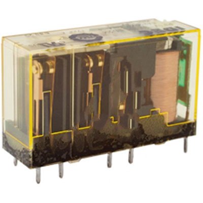
Figure 3.1: Front view of the IDEC RF1V-3A3BL-D24 Force Guided Relay. This image shows the transparent housing, revealing the internal contacts, coil, and PCB terminals at the base. The relay is designed for direct PCB mounting.
Key Features:
- Force Guided Contacts: Ensures reliable operation in safety circuits.
- Contact Configuration: 3 Normally Open (NO) and 3 Normally Closed (NC) contacts.
- Coil Voltage: 24V DC.
- Indication: Integrated LED for coil status.
- Mounting: PCB terminals for direct board mounting.
4. Setup and Installation
Before installation, ensure the power supply is disconnected. Verify that the relay specifications match your application requirements.
- Prepare PCB: Ensure the Printed Circuit Board (PCB) has the correct footprint for the RF1V-3A3BL-D24 relay's terminals.
- Insert Relay: Carefully align the relay's pins with the corresponding holes on the PCB. Apply gentle, even pressure to seat the relay fully.
- Solder Connections: Solder each terminal pin to the PCB using appropriate soldering techniques. Ensure strong, clean solder joints for reliable electrical contact.
- Wiring: Connect the coil power (24V DC) to the designated coil terminals. Connect the load circuits to the NO and NC contact terminals as per your application's control logic. Refer to the product datasheet for detailed pinout diagrams.
- Verify Connections: Double-check all wiring for correctness and secure connections before applying power.
5. Operating Instructions
Once installed and wired correctly, the relay operates by energizing its coil.
- Coil Energization: Apply 24V DC to the coil terminals. The integrated LED will illuminate, indicating that the coil is energized.
- Contact Operation: When the coil is energized, the Normally Open (NO) contacts will close, and the Normally Closed (NC) contacts will open.
- Coil De-energization: Remove the 24V DC supply from the coil terminals. The LED will turn off, and the contacts will return to their original state (NO contacts open, NC contacts close).
- Force Guided Mechanism: The force-guided mechanism ensures that all contacts move together, preventing a dangerous state where one contact might stick while others release. This is critical for safety applications.
6. Maintenance
The IDEC RF1V-3A3BL-D24 relay is designed for long-term reliability and typically requires minimal maintenance. However, periodic inspection is recommended.
- Visual Inspection: Regularly inspect the relay for any signs of physical damage, discoloration, or loose connections. The transparent casing allows for easy visual checks of the contacts.
- Environmental Check: Ensure the operating environment remains within specified temperature and humidity limits and is free from excessive dust or corrosive substances.
- Contact Integrity: While the force-guided mechanism enhances safety, if the relay is subjected to severe overloads or short circuits, inspect the contacts for pitting or carbon buildup. If significant damage is observed, replace the relay.
- Cleaning: If necessary, gently clean the exterior of the relay with a dry, soft cloth. Do not use solvents or abrasive cleaners.
7. Troubleshooting
This section provides guidance for common issues. For problems not listed here, contact IDEC technical support.
| Problem | Possible Cause | Solution |
|---|---|---|
| Relay does not energize (LED off) | No power to coil; Incorrect coil voltage; Open circuit in coil wiring; Damaged coil. | Check 24V DC power supply; Verify wiring connections; Test coil resistance (replace if open). |
| Contacts do not switch | Coil not energizing (see above); Contacts welded/stuck; Mechanical obstruction. | Ensure coil energizes; Replace relay if contacts are damaged or stuck. |
| Intermittent operation | Loose wiring connections; Unstable power supply; Excessive vibration. | Secure all connections; Stabilize power supply; Mount relay securely to reduce vibration. |
8. Specifications
Detailed technical specifications for the IDEC RF1V-3A3BL-D24 Force Guided Relay.
| Parameter | Value |
|---|---|
| Model Number | RF1V-3A3BL-D24 |
| Contact Configuration | 3 Normally Open (NO), 3 Normally Closed (NC) |
| Coil Voltage | 24V DC |
| Indication | Integrated LED |
| Terminal Type | PCB Terminals |
| Force Guided | Yes |
| Manufacturer | Idec |
| Item Weight | 0.8 ounces |
| ASIN | B00DWICZ1E |
9. Warranty and Support
For specific warranty information regarding the IDEC RF1V-3A3BL-D24 relay, please refer to the official IDEC Corporation warranty policy available on their website or contact your authorized IDEC distributor.
For technical support, product inquiries, or service, please contact IDEC Corporation directly or your local IDEC representative. Contact information can typically be found on the official IDEC website (us.idec.com).


