1. Introduction
The QIACHIP 433Mhz Universal Wireless Remote Control Switch system provides a convenient solution for wirelessly controlling various electrical devices. This system is suitable for a wide range of applications in homes, farms, factories, offices, laboratories, and supermarkets.
Typical applications include:
- Remote control of garage doors, electric doors, house doors, shutter doors, expansion doors, gate doors, and road gates.
- Remote control of electric curtains, water pumps, fans, lamps, LED lights, bulbs, and ventilation devices.
- Signal transmission for various automation tasks.
- Remote control for motor positive and negative rotation, and motor switching for DIY projects.
This manual provides detailed instructions for setting up, operating, and maintaining your QIACHIP remote control switch system.

Figure 1: QIACHIP Remote Control and Receiver Module
Video 1: Product Overview and Demonstration
2. Specifications
2.1 Receiver Module (Model: KR2202-4)
| Feature | Specification |
|---|---|
| Product Type | Dual Channel Remote Control Switch |
| Encoding Type | Intelligent Learning Code |
| RF Working Mode | Superheterodyne Reception |
| Modulation Mode | ASK |
| Working Modes | Momentary, Toggle, Latching |
| RF Frequency | 433MHz |
| Input Voltage | AC 85V~250V |
| Standby Current | <8.5mA |
| Receiving Sensitivity | >97dbm |
| Remote Control Range | >50m (Free Space) |
| Wired Connection Way | Fixed Wiring Pillar |
| Output Terminal | NO (Normal Open), COM (Commonality End), NC (Normally Closed End) |
| Color | Green (PCB Board), White (Outside Shell) |
| Circuit Board Size | 7.3 x 5.2 x 2.5 cm |
| Channels | 2 |
| Certification | CE |

Figure 2: Close-up view of the KR2202-4 Receiver Module
2.2 Remote Transmitter (Model: KT05-4)
| Feature | Specification |
|---|---|
| Model Number | KT05-4 |
| Operating Frequency | 433MHz |
| Power Source | 3V Coin Cell Button Battery (included) |
| Material | PVC |
| Buttons | 2 Buttons (A and B) |
| Size | 59mm x 28mm x 8mm |
| Operating Voltage | 3V |
| Operating Current | 12mA |
| Transmitting Power | 10mw |
| Modulation Mode | ASK (AM) |
| Encoding Type | Learning |
| Transmission Distance | 20-50 m |

Figure 3: Remote Control Transmitter Features
3. Setup and Wiring
Safety Warning: Before performing any wiring, ensure that the power supply to the circuit is completely disconnected to prevent electric shock. If you are unsure about electrical wiring, consult a qualified electrician.
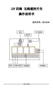
3.1 Receiver Terminal Overview
The receiver module features fixed wiring pillars for secure connections. The output terminals are labeled as NO (Normal Open), COM (Commonality End), and NC (Normally Closed End).

Figure 4: Receiver Module Terminal Labels
3.2 Wiring for AC Loads (e.g., Lights)
To control an AC load such as a light, connect the live (L) and neutral (N) wires of your AC power supply to the 'IN' terminals on the receiver. Then, connect your AC load to the appropriate output terminals (NO, COM, NC) based on your desired operation (e.g., normally open or normally closed circuit).

Figure 5: Wiring Diagram for AC Loads (e.g., Lights)
3.3 Wiring for DC Motor Forward and Reverse Control
For controlling the forward and reverse rotation of a DC motor, refer to the specific wiring diagrams below. Ensure correct polarity and connections to avoid damage to the motor or receiver.

Figure 6: DC Motor Forward and Reverse Wiring Diagram

Figure 7: Three-wire Motor Forward and Reverse Wiring Diagram
4. Operating Instructions
The receiver supports three working modes: Momentary, Toggle, and Latching. You can configure the receiver to operate in your desired mode by following the code learning procedures below.
4.1 Working Modes Explained
- Momentary Mode: Press and hold the remote button, the relay connects. Release the remote button, the relay disconnects.
- Toggle Mode: Press the remote button once, the relay connects. Press the same remote button again, the relay disconnects.
- Latching Mode: Press remote button A, the relay connects. Press remote button B, the relay disconnects. (Requires two distinct buttons for ON/OFF).
4.2 Clearing the Code
To clear all learned remote control codes from the receiver:
- Press the Learning Button on the receiver module 8 times consecutively.
- The codes will be cleaned. After this, all previously paired remote controls will no longer work with this receiver.
4.3 Learning the Code (Pairing Remote)
General Steps: After clearing the code, or if you are adding a new remote, follow these steps based on your desired working mode.
4.3.1 Momentary Mode Learning
- Press the Learning Button on the receiver once. The receiver enters momentary setting mode.
- Wait for a moment; the LED indicator on the receiver will turn off, indicating it is in learning state.
- Push the desired button on your remote control. The LED indicator on the receiver board will flash and then turn off.
- After approximately 3 seconds, the LED indicator will turn on again, signifying successful learning.
4.3.2 Toggle Mode Learning
- Press the Learning Button on the receiver twice. The receiver enters toggle setting mode.
- Wait for a moment; the LED indicator on the receiver will turn off, indicating it is in learning state.
- Press the desired button on your remote control. The LED indicator on the receiver board will flash and then turn off.
- After approximately 3 seconds, the LED indicator will turn on again, signifying successful learning.
4.3.3 Latching Mode Learning
Note: For latching mode, you need to learn two different buttons on your remote control: one for ON and one for OFF.
- Press the Learning Button on the receiver three times. The receiver enters latching mode.
- Wait for a moment; the LED indicator on the receiver board will flash and then turn off.
- Press remote button A (for ON). The LED will flash 5 times.
- Press remote button B (for OFF). The LED will flash 5 times.
- After approximately 3 seconds, the LED indicator will turn on again, signifying successful learning. Now, button A will turn the relay ON, and button B will turn it OFF.
5. Maintenance
- Cleaning: Use a soft, dry cloth to clean the remote control and receiver module. Avoid using liquids or abrasive cleaners.
- Environment: Keep the devices away from moisture, extreme temperatures, and direct sunlight.
- Battery Replacement (Transmitter): The remote control transmitter is powered by a 3V coin cell button battery. If the remote's range decreases or the indicator light becomes dim, replace the battery with a new one of the same type.
- Avoid Impact: Do not drop or subject the devices to strong impacts, as this can damage internal components.
6. Troubleshooting
- Remote Not Responding:
- Ensure the receiver is powered correctly (AC 85V~250V).
- Check the battery in the remote control. Replace if necessary.
- Verify that the remote is paired correctly. If unsure, try clearing the code and re-learning it according to the instructions in Section 4.3.
- Limited Remote Range:
- Ensure there are no significant obstructions (e.g., thick walls, metal objects) between the remote and the receiver.
- Check for potential sources of RF interference in the vicinity.
- The specified range is for free space; actual range may vary indoors.
- Relay Not Switching:
- Confirm the wiring to the load is correct and secure (refer to Section 3).
- Ensure the load's power requirements do not exceed the receiver's relay capacity.
- Accidental Triggering/Unintended Operation:
- This could indicate interference or a need to re-pair the remote. Clear all codes and re-learn only the desired remote(s).
7. User Tips
- Multiple Remotes: The system is designed to support multiple remote controls. You can pair additional transmitters to a single receiver by repeating the learning process for each new remote. This is useful for multi-user access or having backup remotes.
- Testing Modes: Before final installation, test each working mode (Momentary, Toggle, Latching) to ensure you select the one that best suits your application.
- Clear Codes Regularly: If you lose a remote or suspect unauthorized access, clear all codes from the receiver immediately and re-pair only your active remotes.
8. Warranty and Support
For technical assistance, troubleshooting beyond this manual, or warranty inquiries, please contact the manufacturer or your point of purchase. Keep your purchase receipt as proof of purchase.