Acrel AWT100 Data Conversion Module

Overview
At present, wireless technology relies on the advantages of easy deployment, low construction cost, and wide application environment. Data diversification has gradually become an important direction for network development and application in the future industrial Internet. AWT100 data conversion module is a new data conversion DTU launched by Acrel Electric. Communication data conversion includes 2G, 4G, NB, LoRa, LoRaWAN, GPS, WiFi, CE, DP and other communication methods. The downlink interface provides a standard RS485 data interface. It can be easily connected to power meters, RTUs, PLCs, industrial computers and other equipment, and only needs to complete the initial configuration at a time to complete the data collection of the MODBUS equipment; at the same time, the AWT100 series of wireless communication terminals use powerful micro-processing chips to cooperate Built-in watchdog technology, reliable and stable performance.The appearance is shown in Figure 1.

Figure 1 AWT100 Wireless communication terminal
Features
- Using single-mode guide rail shape, small size, flexible and convenient installation;
- A variety of mainstream wireless modules, suitable for various on-site environments;
- Multiple hardware interface modes, easy to use with other products;
- Rich communication interface protocols can meet the different needs of customers.
The applicable industries are as follows:
- Wireless meter reading;
- Building automation and security;
- Robot control;
- Power distribution network monitoring, power load monitoring;
- Intelligent lighting control;
- Automatic data collection;
- Industrial remote control and telemetry;
- Highway and railway data transmission;
- Other power and industrial control industries, etc.
Product Model

Features
- Support serial MODBUS RTU protocol data collection, and communicate with Acrel server through Acrel platform protocol①.
- Support data collection of up to 30 MODBUS RTU devices.
- Support the collection of 5 register address fields for each MODBUS device, and the address range of each register does not exceed 64.
- Support to preset alarm address and alarm value to trigger alarm for each MODBUS address range. There are currently at most 5 alarm addresses in each address domain.
- Support server MODBUS or LoRa transparent transmission communication.
- Support fixed IP and dynamic domain name resolution methods to connect to the data center.
- Support transparent transmission protocol, general mode (active round copy, regular report), MQTT protocol, smart power wireless protocol, prepaid wireless protocol It can be customized and developed.
- AWT100-LW wireless communication terminal can upload data to the server through LoRa communication.
- AWT100-GPS wireless module can measure geographic location, obtain latitude and longitude and satellite time.
- The AWT100-WiFi wireless module can automatically access the WIFI hotspot according to the hotspot name and password, realize the transparent transmission of 485 and WIFI data, and also use our cloud platform protocol.
- AWT100-CE can realize data transmission from 485 to Ethernet. It can be used as a TCP client and supports transparent transmission or our cloud platform protocol.
- AWT100-DP can realize data transmission from ProfiBus to MODBUS.
Note: ①AWT100-2G/NB/4G wireless communication terminal can communicate with the Acrel server through the Acrel platform protocol.
Typical Applications
Typical application connections are shown in Figure 2 and Figure 3. Connect the on-site 485 devices to the AWT100 wireless communication terminal. The AWT100 wireless communication terminal will actively collect the data of the 485 device according to its own configuration, and then communicate with the Acrel server.

Figure 2 AWT100-2G/NB/4G Typical application of wireless communication terminal

Figure 3 AWT100-LoRaTypical application of wireless communication terminal
Technical Parameters
|
Parameter Name |
AWT100-4G |
AWT100-NB |
AWT100-2G |
AWT100-LoRa
AWT100-LW |
| LTE-FDD B1 B3 B5 B8 | GSM 850 | |||
| Working | LTE-TDD B34 B38 B39 B40 B41 | H-FDD B1 B3 B8 B5 | EGSM 900 | LoRa 460 510MHz |
| frequency | CDMA B1 B5 B8 | B20 | DCS 1800 | |
| GSM 900/1800M | PCS 1900 |
| Transmission rate | LTE-FDD
Maximum downlink rate 150Mbps Maximum uplink rate 50Mbps LTE-TDD Maximum downlink rate130Mbps Maximum uplink rate 35Mbps CDMA Maximum downlink rate 3.1Mbps Maximum uplink rate 1.8Mbps GSM Maximum downlink rate 107Kbps Maximum uplink rate 85.6Kbps |
Maximum downlink rate 25.2Kbps Maximum uplink rate 15.62Kbps | GPRS
Maximum downlink rate 85.6kbps Maximum uplink rate 85.6kbps |
LoRa 62.5kbps |
| Downlink | RS485 Communication | |||
|
Uplink |
4G Communication |
NB-IoT
Communication |
2G Communication |
LoRa
Communication |
| SIM card
voltage |
3V,1.8V |
/ |
||
|
Working current |
Static power:≤1W,Transient power consumption:≤3W |
Static power:
≤0.5W, Transient power consumption:≤1W |
||
| Antenna
interface |
50Ω/SMA(Faucet) |
|||
| Serial port type | RS-485 | |||
| Baud rate | 4800bps、9600bps、19200bps、38400bps(default 9600bps) | |||
| Operating
Voltage |
DC24V 或 AC/DC220V① |
|||
| Operating
temperature |
-10℃~55℃ |
|||
| Storage
temperature |
-40℃~85℃ |
|||
| Humidity range | 0~95% Non-condensing | |||
| Parameter Name | AWT100-LoRa | AWT100-LW | AWT100-LW868 | AWT100-LW923 | AWT100-LORAHW |
| Working frequency | 460~510MHz | 470MHZ | 863-870MHZ | 920-928MHZ | 860-935MHZ |
| Transmission rate | LoRa 62.5kbps | ||||
| Downlink | RS485 Communication | ||||
| Uplink | LoRa Communication | ||||
| Working current | Static power:≤0.5W,Transient power consumption:≤1W | ||||
| Antenna interface | 50Ω/SMA(Faucet) | ||||
| Serial port type | RS-485 | ||||
| Baud rate | 4800bps、9600bps、19200bps、38400bps(default 9600bps) | ||||
| Operating Voltage | DC24V 或 AC/DC220V① | ||||
| Operating temperature | -10℃~55℃ | ||||
| Storage temperature | -40℃~85℃ |
| Humidity range | 0~95% Non-condensing |
| parameter name | AWT100-GPS | AWT100-WiFi | AWT100-CE | AWT100-DP |
|
Work |
Positioning accuracy: 2.5-5m | support 2.4G frequency band
WiFi rate: 115200bps |
Ethernet rate 10/100M adaptive | Profibus address: 1~125. (Note) |
| Downlink | RS485 Communication | |||
| Uplink | GPS positioning | WiFi wireless | Ethernet
communication |
Profibus
communication |
|
Working current |
Static power consumption:≤1W,transient power consumption:≤3W |
Static power consumption:
≤0.5W, transient power consumption: ≤1W |
||
| interface | 50Ω/SMA(Faucet) | RJ45 | DP9 | |
| Serial port type | RS-485 Communication | |||
| Baud rate | 4800bps、9600bps、19200bps、38400bps(Default 9600bps) | |||
| Operating
Voltage |
DC24V or AC/DC220V① | |||
| Operating
temperature |
-10℃~55℃ | |||
| Storage
temperature |
-40℃~85℃ | |||
| Humidity range | 0~95% Non-condensing | |||
Note:
- C/DC220V power supply requires external AWT100-POW power supply module.
- Profibus communication rate: 9.6kbps, 19.2kbps, 45.45kbps, 93.75kbps, 187.5kbps, 500kbps, 1.5Mbps, 3Mbps, 6Mbps, 12Mbps. Data exchange length: total input length<=224 bytes, total output length<=224 bytes. The number of downstream instruments connected: 1~80.
Installation and wiring instructions
Outline and installation dimensions

Product installation
Adopt standard DIN35mm rail type installation.
- Terminals and wiring
- AWT100-2G/NB/4G/LoRa/LW/GPS/WiFi terminal and wiring

The function of the network port is the power interface and the RS485 interface. The specific definitions are as follows:

AWT100-CE terminal and wiring
AWT100-DP terminal and wiring

AWT100-2G/NB/4G/LoRa/LW/GPS/WiFi/CE/DP side interface definition
Note: The two interfaces of network port and terminal can only be used by one of the two (except for AWT100-CE), and cannot be used at the same time.
Power module terminal definition

- Auxiliary power(AC/DC 220V)
- Side interface definition

The side interface is used for the AWT100 wireless communication terminal to supply power through the AWT100-POW power module AC220V. The AWT100 wireless communication terminal is connected to the AWT100-POW power supply module through pins and fixed together by a buckle. The connection diagram is shown in Figure 4:

Installation Notes:
- When the AWT100 wireless communication terminal is powered by the AWT100-POW power supply module, the auxiliary power terminal and network port of the AWT100 wireless communication terminal The 24V power supply cannot be connected again.
- Antenna installation, the antenna interface of the AWT100 wireless communication terminal adopts 50Ω/SMA (female), and the external antenna must be an antenna suitable for the working band. If other unmatched antennas are used, it may affect or even damage the equipment.
- When installing the SIM card, make sure that the device is not powered on. The SIM card of the AWT100 wireless communication terminal adopts a card tray installation method. You need to put the SIM card in the card tray correctly, and then insert the SIM card into the card holder of the device.
6.4 Panel light definition
6.4.1 Definition of AWT100-2G/NB/4G wireless communication terminal panel lights
| LINK(Green) | RSSI(Red) | COMM(Orange) | ||
| The green indicator flashes for 2 | The red indicator flashes | The orange indicator | ||
| seconds, the wireless module is being | for 3 seconds to indicate | flashes to indicate that | ||
| initialized | that the signal is less than | there is network data | ||
| The green indicator flashes | for | 1 | 20% | communication |
| second, connecting to the server | ||||
| The green indicator light is always on | ||||
| to indicate that the server is connected | ||||
| and the signal strength is greater than | ||||
| 20% | ||||
6.4.2 Definition of AWT100-LoRa wireless communication terminal panel light
| RUN(Green) | LoRa(Red) | COMM(Orange) |
| The green indicator light is always on, indicating that the meter has been able to operate
normally. |
The red indicator light flashes for 1 second when there is a LoRa signal to receive and send
data. |
The orange indicator light flashes for 1 second when there is 485 to receive and
send data. |
6.4.3 AWT100-LW Definition of wireless communication terminal panel lights

6.4.4 AWT100-GPS Definition of wireless communication terminal panel lights
| RUN(Green) | LoRa(Red) |
| The green indicator light is always on, indicating that the power supply voltage
is normal. |
After the positioning is successful, it flashes for 1 second and the green indicator light is off |
6.4.5 AWT100-WiFi Definition of wireless communication terminal panel lights
| RUN(Green) | LoRa(Red) |
| Blinking in connection, the connection
is successful. |
Blinking when there is data transmission |
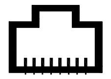
AWT100-CE Ethernet communication panel light definition
- RJ45: Ethernet interface
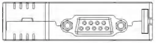
AWT100-DP data conversion module panel light definition
- Digital tube: display Profibus address (1~99)
- USB interface: configure the module parameters, connect to the upper computer
- DB9 interface: communicate with upstream DP equipment, Profibus_DP protocol
485 interface: communication with downstream instruments, Modbus_Rtu protocol
AWT100-POW Panel light definition of power module
The green indicator light is always on to indicate that the power module is operating normally. If the indicator light is off, it indicates that the module is not powered on or is faulty.
7 AWT100 Wireless Communication Terminal User Guide
AWT100 wireless communication terminal configuration
Before using the AWT100 wireless communication terminal, the user can configure the parameters of the AWT100 wireless communication terminal according to the actual situation. The operation process is as follows:
- The AWT100 wireless communication terminal is powered on, and the working indicator of the AWT100 wireless communication terminal flashes, indicating that the AWT100 wireless communication terminal has started to work.
- Start the configuration software of the AWT100 wireless communication terminal, which consists of the computer serial port parameter area, information display area, parameter setting area, parameter reading and setting buttons, as shown in Figure 5.
The AWT100 wireless communication terminal configuration software can read and set parameters, and can test the working status of the AWT100 wireless communication terminal. Please confirm the serial port number of the currently used serial port, modify the serial port number, and keep the serial port baud rate consistent, and click “open serial port” after confirmation. After the serial port is successfully connected to the host computer (the host status box turns green)
- WT100-2G/4G/NB wireless communication terminal parameter reading Click the in the upper right corner
 ,to display all the parameter values inside the AWT100 wireless communication terminal, as shown in Figure 5.
 - AWT100-2G/4G/NB wireless communication terminal parameter setting Click the parameter value to be modified, directly input or modify the corresponding parameter value,Click the button in the upper right corner
 to complete the parameter setting.
7.2 AWT100 wireless communication terminal parameter description
- AWT100-2G/4G/NB wireless communication terminal connection status
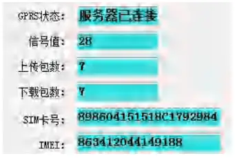
- GPRS status
Display the connection status between the AWT100-2G/4G/NB wireless communication terminal and the server. - Signal value
Indicates the signal strength of the connection between the AWT100-2G/4G/NB wireless communication terminal
and the server. The larger the value, the stronger the signal. - Number of upload packages
Indicates the number of data packets uploaded by the AWT100-2G/4G/NB wireless communication terminal to the server. - Number of download packages
Indicates the number of data packets received from the server by the AWT100-2G/4G/NB wireless communication terminal. - SIM card number
Insert the SIM card number of the AWT100-2G/4G/NB wireless communication terminal. - IMEI
The device identification code of the AWT100-2G/4G/NB wireless communication terminal.
- GPRS status
- AWT100 wireless communication terminal software information
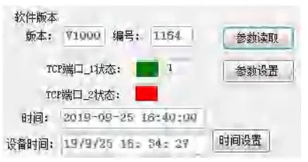
- version
Software version of AWT100 wireless communication terminal。 - serial number
Software version of AWT100 wireless communication terminal。 - TCP port_1 status
Green indicates that the AWT100-2G/4G/NB wireless communication terminal is successfully connected to the server port .Red indicates that the AWT100-2G/4G/NB wireless communication terminal failed to connect to the server port. - TCP port_2 status
TCP port_2 is currently not used。 - Time
The system time of the current computer. - Equipment time
Equipment time of wireless communication terminal AWT100-2G/4G/NB,Click the device time of the AWT100-2G/4G/NB wireless communication terminal can be synchronized with the current computer system time.
- version
- Data area
The first box in the data area indicates the starting MODBUS address of the register of the downstream device, and the second box indicates the meter reading length (not more than 64), for example ,indicates to start meter reading from the downstream device address 1000H, the address length is 2a (hexadecimal).
- Parameter area
The parameter area can be selected from the drop-down . The data in the parameter area can be uploaded to the server once when the device is powered on, once a day, or when the data changes.
 - Alarm word
setting 10 alarm words of addresses can be set, and data will be uploaded when the alarm word of the set address changes. - Number of equipment
The number of meter readings is set, and the data collection of up to 30 MODBUS RTU devices is supported. - Number of meter reading segments
The number of register address fields collected by each MODBUS device shall not exceed 5.
Number of alarm segments
The total number of alarm words to be set is up to 10, and the number of settings should be consistent with the number of alarm words. - Waiting time
Wait for the response time of the downstream device.
Number of timeouts
If the number of reconnections of the downlink device exceeds the specified number, it is considered that the downlink device is disconnected from the AWT100 wireless communication terminal. - Downlink
The default 485 bus communication (LoRa communication is optional). - Downstream device address type
Use the MODBUS address to read the meter and the serial number (14-digit) address to read the meter. - Downstream equipment type (Reserved)
- Parameter area
- AWT100-2G/4G/NB wireless communication terminal network setting parameters
 IP_1 address
- The IP address of the first server to connect to.
- IP_1 port
Connect the IP port of the first server. - IP_2 address
Connect to the IP address of the second server. - IP_2 port
Connect the IP port of the second server. - Domain name
setting_1 The domain name of the first server to connect to. - Domain name setting_2
The domain name of the second server to connect to. - Device number
Device serial number (14 digits). - Data upload interval
The data upload time interval in the data area, the default is 5min. - Parameter upload interval
The data upload time interval in the data area, the default is 1440min. - Connection method
The connection address method with the service area (IP/domain name). - Total number of TCP connections
The number of servers connected at the same time. - Network timeout
The time to wait for a response from the server. - Number of network timeout retries
The number of retransmissions to the server.
- AWT100-2G/4G/NB wireless communication terminal protocol setting parameters

- Coding factor 1
- Coding factor 2
- Code classification
- Process coding
- ST
- MN
- Communication protocol options
- Protocol internal options The above are the relevant agreement parameters involved in each area of the HJ212 environmental protection agreement, which depends on the agreement.
- Downlink device status of AWT100-2G/4G/NB wireless communication terminal

- Downlink device status Click can
 read the status of all downstream devices .Click
  can read the status of a single downstream device.Click
  can write the serial number of the downstream device (when using the MODBUS address to read the meter,there is no need to write the serial number).
 - Red indicates that the downstream device is offline.
- Green indicates that the downstream device is online .E.g

.Indicates that the device with the serial number 20190903000001 is online.
- Downlink device status Click can
- AWT100-LoRa Wireless communication terminal relay/transmission parameters Relay/transparent transmission setting options are used to set the wireless parameter settings of the
AWT100-LoRa wireless communication terminal, Click the button can read the wireless parameter settings of the AWT100-LoRa wireless communication terminal. After modifying the
wireless parameters of the AWT100-LoRa wireless communication terminal, Click the button to complete parameter setting。
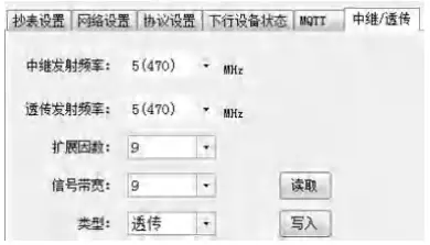
- Relay transmission frequency
The frequency of relay transmission: 460 ~510MHz.If the working mode of the AWT100-LoRa wireless communication terminal is set to relay mode, the relay transmission frequency must be inconsistent with the transparent transmission frequency. - Transparent transmission frequency
The frequency of transparent transmission: 460~510MHz. - Expansion factor
LoRa spreading factor - Signal bandwidth
LoRa signal bandwidth - Type
Set the working mode of the AWT100-LoRa wireless communication terminal.There are two ways to choose from: transparent transmission and relay.
- Relay transmission frequency
- AWT100-GPS positioning module parameter settings

- Positioning interval: latitude and longitude refresh interval.
- Positioning time: positioning satellite time.
AWT_GPS modbus register address table and description Adress Register number
name Number of registers
Attributes(W /R)
Description 0000H 1 contact address
1 W/R Value range 1~127, universal address 0 0001H 2 Baud rate 1 W/R 0:1200 1:2400 2:4800 3:9600 4:19200 5:38400 6:57600 7:115200
0002H 3 Positionin g interval
1 W/R Value range 100ms~10000ms 0003H
4
Latitude hemispher e
1
R
ASCIICode (0x4E)N,Northern Hemisphere (0x53)S,Southern Hemisphere
0004H 5 latitude
2
R
E.g 3150.7797 -> 31°50′.7797
0005H 6 0006H
7
Transhemi sphere 1
R
ASCII Code (0x45)E,Eastern Hemisphere (0x57)W,Western Hemisphere
0007H 8 longitude
2
R
float E.g 11711.9287 -> 117°11′.9286
0008H 9 0009H 10 Second 1 R UTC time
Minute 000AH 11 Hour 1 R Day 000BH 12 Month 1 R Year Note: Modbus read and write reply delay is 300ms~500ms under the default baud rate of 9600, Therefore, the waiting time of Modbus host should be at least more than 300ms;
- AWT100-WiFiWireless communication module parameter setting

- AP: WIFI hotspot name
- PASS: WIFI hotspot password
- AWT100-CEEthernet data conversion module parameter setting

- AWT100-DP data conversion module parameter setting

How to use
After setting the parameters of the AWT100 wireless communication terminal, confirm that the downlink equipment is operating normally and the gateway can communicate with the AWT100 wireless communication terminal normally. Wait for the AWT100 wireless communication terminal to establish a connection with the server, and send the device number to the server to distinguish the devices. At the same time, the AWT100 wireless communication terminal will poll the downstream device to query the online downstream device according to the set query address range and query register address field, and send the polled data to the server for reporting.
Headquarters: Acrel Co., LTD.
- Address: No.253 Yulv Road Jiading District, Shanghai,China
- TEL.: 0086-21-69158338 0086-21-69156052 0086-21-59156392 0086-21-69156971 Fax: 0086-21-69158303
- Web-site: www.acrel-electric.com
- E-mail: ACREL008@vip.163.com
- Postcode: 201801
- Manufacturer: Jiangsu Acrel Electrical Manufacturing Co., LTD.
- Address: No.5 Dongmeng Road,Dongmeng industrial Park, Nanzha Street,Jiangyin City,Jiangsu Province,China
- TEL./Fax: 0086-510-86179970
- Web-site: www.jsacrel.com
- Postcode: 214405
- E-mail: JY-ACREL001@vip.163.com
Documents / Resources
 |
Acrel AWT100 Data Conversion Module [pdf] Installation Guide AWT100 Data Conversion Module, AWT100, Data Conversion Module, Conversion Module, AWT100 Conversion Module, Module |


